• Welcome to ClassicBroncos! - You are currently viewing the forums as a GUEST. To take advantage of all the site features, please take a moment to register. It's fast, simple and absolutely free. So please join our community today!
    If you have problems registering or can't log into your account, please contact Admin.

Engine Swap: Cummins R2.8

ntsqd

heratic car camper
Joined
Jan 30, 2005
Messages
3,239
Loc.
Upper SoKA
I once owned a diesel VW Caddy (Rabbit pick-up) at/near sea level on this Coastal Desert. Ginormous 1.6L NA diesel that made a whopping 52 HP peak. I had a turbo on it from the beginning and thought that was slow. Then the idling vibes caused some damage to the turbo's turbine scroll and I needed to drive the vehicle ~500 miles while it was being repaired. So I built the bits to be able to temporarily drive it NA. Never again, that was horrible. The turbo was worth an easy 15 HP on that engine, and it lacked boost fuel enrichment.

If the diesel is designed to be turbo'd from the start (the Caddy was not) then the turbo is an integral part of power production and altitude compensation is more of a by-production than the reason for it to be there at all.
 

ame

Full Member
Joined
Jun 28, 2016
Messages
191
Neat.

Might also look at rear end ratio to help with lower rpm. I was going to buy a turbo diesel pickup and noted none of them came with less than a 3.5 ratio, no 4.11, because you are using torque not HP.

To be fair to the 351 though, you could have turbo charged that to keep the power at altitude like the diesel. I am not sure if or how much the diesel turbo boosts at sea level, I think it is mainly for altitude compensation.

The only reason you cant get less then a 3.50 ratio on a SRW diesel is fuel economy standards , you can get a DRW in lower ratios.

Turbo vehicles weather gas or diesel will make similar boost pressure at sea level as at altitude, Its based off exhaust heat and drive pressure not altitude.
 

markw

Contributor
Bronco Guru
Joined
Sep 10, 2009
Messages
2,051
I had 4:56 gears in my 7.3 SD for a while. It was not happy at all despite 37" tires. Switched back to 3:70 and 35" and much happier. What would be a good ratio for the 2.8 and 35" tires on a EB? Given a 5 speed OD trans.
 

markw

Contributor
Bronco Guru
Joined
Sep 10, 2009
Messages
2,051
Thinking about a future build. I'd be interested in a 680R if someone came up with an adaptor. Otherwise it would be an AX15. Gears are 4:56 at the moment.
 

ntsqd

heratic car camper
Joined
Jan 30, 2005
Messages
3,239
Loc.
Upper SoKA
3.73's and 315-70R17's work fairly well under our CTD, but there are times where I'm wishing for a second OD. Just don't know that I can justify a GV for that truck.
 

ame

Full Member
Joined
Jun 28, 2016
Messages
191
3.73's and 315-70R17's work fairly well under our CTD, but there are times where I'm wishing for a second OD. Just don't know that I can justify a GV for that truck.

I know of a few GVs that people put behind CTDs and did not last very long, they dont seem to handle torque very well. I have an 06ctd and have had 3.73 , 4.10 and now 4.56 all with 37" tires, the driving characteristics have changed the fuel mileage has actually been very similar with all the gears.
 

ntsqd

heratic car camper
Joined
Jan 30, 2005
Messages
3,239
Loc.
Upper SoKA
Ours is only a 600 ft-lbs 6BT, not a chipped, overly-valved, twin-turbo'd 1000+ ft-lbs monster.

My point was that I'd gear it a little tall and add more low range or doubler if needed rather than gear it short and be wishing for one more gear on the long highway stretches.

EDIT: As to GV's not living behind CTD's, got links? First that I've ever heard of this. Yeah, I can see a built truck chewing one up, but not the normal, mildly tuned truck going down the road.
 
Last edited:

markw

Contributor
Bronco Guru
Joined
Sep 10, 2009
Messages
2,051
I was advised by a couple of transmission shops not to put a GV on my 7.3. I don't recall the reason.
 

ame

Full Member
Joined
Jun 28, 2016
Messages
191
Ours is only a 600 ft-lbs 6BT, not a chipped, overly-valved, twin-turbo'd 1000+ ft-lbs monster.

My point was that I'd gear it a little tall and add more low range or doubler if needed rather than gear it short and be wishing for one more gear on the long highway stretches.

EDIT: As to GV's not living behind CTD's, got links? First that I've ever heard of this. Yeah, I can see a built truck chewing one up, but not the normal, mildly tuned truck going down the road.

I dont have links but have been around the Ram Cummins platform for 15 years and have been very active on threads the whole time, seen lots of issues with external Overdrive units. IIRC it was mostly due to the low RPM and high torque, If you used it responsibly it would probably be ok but any lugging or climbing hills and towing was super hard on them.
 

ntsqd

heratic car camper
Joined
Jan 30, 2005
Messages
3,239
Loc.
Upper SoKA
[hijack]The trans guy who did the auto trans in our CTD saw no problem with putting a GV under the truck. His was an informed opinion in that he is a GV dealer. Though he didn't understand why I would want to, he thought I should put a doubler in it.[/hijack]
 
OP
OP
Digger556

Digger556

Sr. Member
Joined
Aug 8, 2013
Messages
793
Since the question was asked, I compared the Close ratio and Wide ratio version of the ZF against the 2.8's torque curve. There doesn't appear to be an appreciable difference for gears 3,4 & 5, which are of most concern. If you look at Peak torque being the RPM at which you are forced to downshift, 5th-to-4th has no difference and 4th-to-3rd is only a small difference resulting in the wide-ratio version spinning 400 more rpm at the time of down shift. For long climbs in the mountains, I don't like holding more than 3500 rpm for the current engine and that is where the R2.8 makes the most HP.

46285301154_c3c59f8c2d_b.jpg


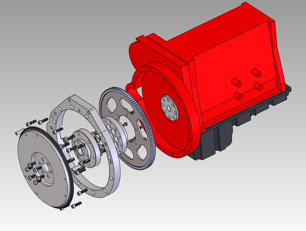
Otherwise, I've been busy measuring and modelling for the transmission adapter. Axis Industries has a few of these and frankly, they've distilled their design down pretty well. My first attempt looked way too much like their's. So much so, I considered trying to contact them again to discuss this project. BUT I had an idea today that simplifies the adapter and gets it away from looking like a copy.
46285300844_5bc83fdeb2_b.jpg


In all likelyhood, the final machining of the adapter's 2nd half will need to be turned while bolted to the first half to minimize runout stackup. A stock Windsor only needs to hold concentricity between the crank OD and the flywheel pilot. This adapter has two pieces and concentricity has to be tightly controlled to prevent excessive runout at the flywheel and pilot bearing.
 

ntsqd

heratic car camper
Joined
Jan 30, 2005
Messages
3,239
Loc.
Upper SoKA
Is that flex-plate a COTS part, or are you having to open up it's register Ø and add the bolt holes? Seems like a lot of parts that will need to have tight tol features or excessive run-out will be the result. Even then it might happen.

What about integrating the 2.8's ring gear onto that first part of the crank flange adapter directly? I designed & built an aluminum "flex-plate/flywheel" with a Pinto starting ring gear for an engine dyno. This assembly sits on the dyno stand so that Sprint car engines, with no flywheel or flex-plate to attach a ring gear to, could be tested as they would be used. Been running that way for decades, Has started everything from a 2.3L Pinto (oddly enough) to a ~600 ci twin turbo tractor puller Olds DRCE with quite literally hundreds of 460's and SBC's in between. Over the years they've worn out a couple ring gears and replaced those, but the flex-plate/flywheel is working fine. I found the dim for the fit of the ring gear to the OD of the "flywheel" in some Pioneer engine parts documentation.

Food for thought anyway.
 
Last edited:
OP
OP
Digger556

Digger556

Sr. Member
Joined
Aug 8, 2013
Messages
793
Is that flex-plate a COTS part, or are you having to open up it's register Ø and add the bolt holes? Seems like a lot of parts that will need to have tight tol features or excessive run-out will be the result. Even then it might happen.

What about integrating the 2.8's ring gear onto that first part of the crank flange adapter directly? I designed & built an aluminum "flex-plate/flywheel" with a Pinto starting ring gear for an engine dyno. This assembly sits on the dyno stand so that Spring car engines, with no flywheel or flex-plate to attach a ring gear to, could be tested as they would be used. Been running that way for decades, Has started everything from a 2.3L Pinto (oddly enough) to a ~600 ci twin turbo tractor puller Olds DRCE with quite literally hundreds of 460's and SBC's in between. Over the years they've worn out a couple ring gears and replaced those, but the flex-plate/flywheel is working fine. I found the dim for the fit of the ring gear to the OD of the "flywheel" in some Pioneer engine parts documentation.

Food for thought anyway.

It's certainly possible. I'm trying to work within my manufacturing limitations and approach this from a commercialization vs one-off point of view. The flex plate is manufactured, but the ring gear is a COTS Cummins P/N. I already have one sitting at my desk. The flex plate will be a simple laser'd part that has its OD and ID touched up to fit perfect. I only have to be concerned about runout between the two adapters. The runout for the flex plate is less of a concern and controlled separately. There is no good way to make the adapter 1-piece due to the Cummins and Ford crank patterns being very similar. I even considered lightening the stock Cummins flywheel and attaching the 2nd half of the adapter to that.
 

ntsqd

heratic car camper
Joined
Jan 30, 2005
Messages
3,239
Loc.
Upper SoKA
More food for thought

For the moment ignoring the starter aspect, would the Cummins flywheel work if it were in the right fore/aft location? I'm wondering if it would then what about simply spacing it back and running a true flex-plate at the crank flange for the starter to work with. Flywheel, spacer, flex-plate stacked up, with longer flywheel bolts. (Not the cheapest option, but ARP will make customs.) The spacer would index on the crank and locate the flywheel while also carrying the pilot bearing. Makes it a pretty simple part with only concentricity of the two piloting features and the parallelism & flatness of the mating surfaces to worry about. Less necessary G,D, & T is a good thing.

Of course, if you're happy with what you have then my blathering is worth what you paid me for it. :)
 
OP
OP
Digger556

Digger556

Sr. Member
Joined
Aug 8, 2013
Messages
793
For the moment ignoring the starter aspect, would the Cummins flywheel work if it were in the right fore/aft location? I'm wondering if it would then what about simply spacing it back and running a true flex-plate at the crank flange for the starter to work with. Flywheel, spacer, flex-plate stacked up, with longer flywheel bolts. (Not the cheapest option, but ARP will make customs.) The spacer would index on the crank and locate the flywheel while also carrying the pilot bearing. Makes it a pretty simple part with only concentricity of the two piloting features and the parallelism & flatness of the mating surfaces to worry about. Less necessary G,D, & T is a good thing.

Of course, if you're happy with what you have then my blathering is worth what you paid me for it. :)

I considered that, and it's not a bad option. The drawback would be the need to custom machine the Cummins flywheel to accept the Ford pressure plate and pilot bearing.

One unknown would be the possibility of mixing a Cummins/Getrag pressure plate with the Ford friction disc and a custom pilot bearing.
 

ntsqd

heratic car camper
Joined
Jan 30, 2005
Messages
3,239
Loc.
Upper SoKA
I have a Camaro V6 T5 behind a Mopar 170 Slant 6 in a '65 Valiant 2 door. It uses a '00 2.2L S-10 disc (right spline size & OD) and pressure plate only because there were no diaphragm PP's made for the Slant's original clutch PP bolt pattern, and it gained me a slight increase in disc diameter that still fit on the OEM flywheel. Drilled the new PP bolt pattern on a manual mill with a rotary table that was a bit small for the job. If the car doesn't sell I eventually plan to have Wilcap make me a replacement steel flywheel.

Clearly the PP that the Cummins flywheel accepts will handle the power (which was a known weakness with the Slant's OEM PP). So the only challenge that I see in that aspect of this approach is to find a disc that works with the Cummins designated PP that has the correctly splined hub for the ZF's input shaft. I used Centerforce's online documentation to sort out all of my options for the Slant. I'd think it should be easy enough to find a disc that will work, and then work backwards to it's application. I made note of the application, but used a Centerforce II clutch on the Slant.
Assuming that it can be done that way I would put the pilot bearing in the spacer rather than the flywheel. I would also try to make the Cummins flywheel work without any mods. That way it's a simple R&R for a possible wear part should that ever need to happen.
 
Last edited:
OP
OP
Digger556

Digger556

Sr. Member
Joined
Aug 8, 2013
Messages
793
Time for update.

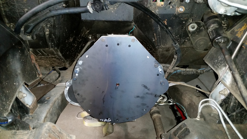
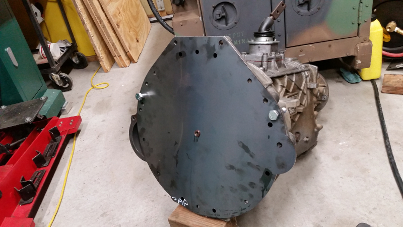
This adapter has consumed a lot of time in order to get it correct the first time. I felt the dimensions for the Cummins side of the adapter were pretty solid, but the dimensions for the Windsor block side of the adapter came mostly from the internet and we all know how reliable the internet is. Particularly, one dimension for the transmission bolt hole was different depending on the source. I needed to verify hole positions as best as possible before proceeding. I created a sheet metal part that contained all the holes from both sides of the adapter plus a pilot hole to align the input shaft to and had it cut out at work.

I fit it to both ZF5s and the R2.8 and confirmed holes at least looked correct. Several holes have spacing that needs to be accurate to within a thousandth of an inch or so, which is hard to verify accurately. The other holes could be +/- 0.10".
47456747772_3a74450c13_o.jpg

47456747672_147894735e_o.jpg

47456747242_e218eac770_o.jpg


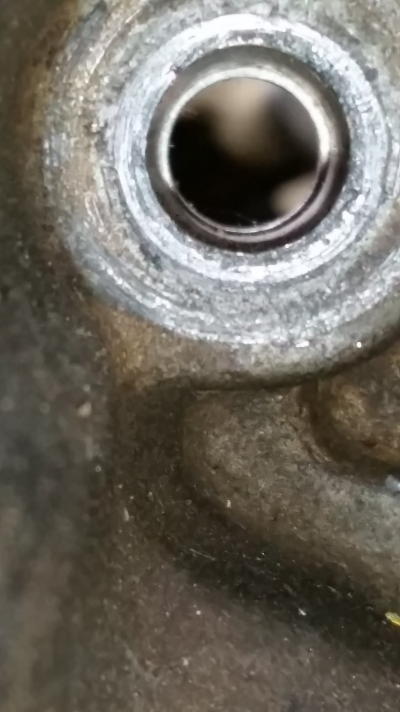
The mounting hole in question looks well centered based on the dimension I assumed was correct, but there is enough slop in this hole it likely doesn't matter.
47456747212_efae373b13_o.jpg
 
OP
OP
Digger556

Digger556

Sr. Member
Joined
Aug 8, 2013
Messages
793
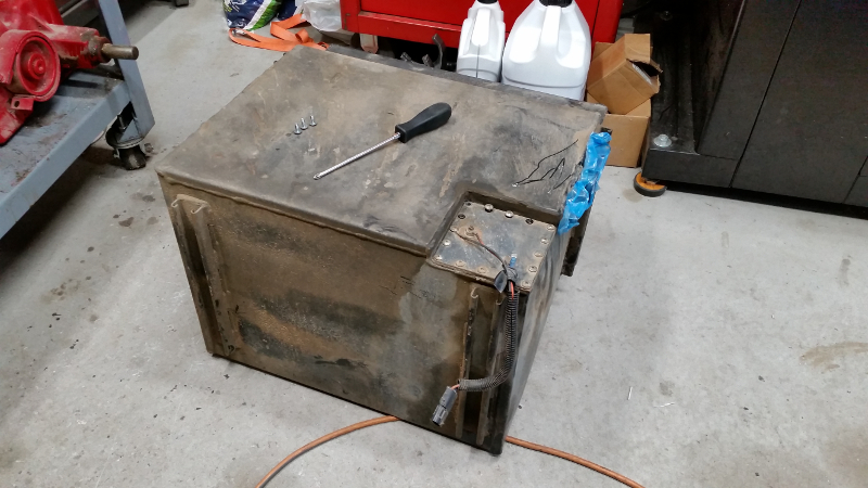
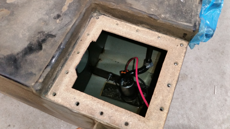
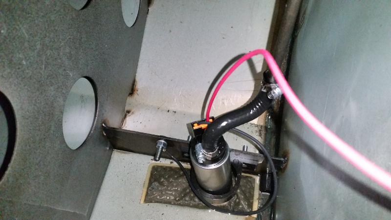
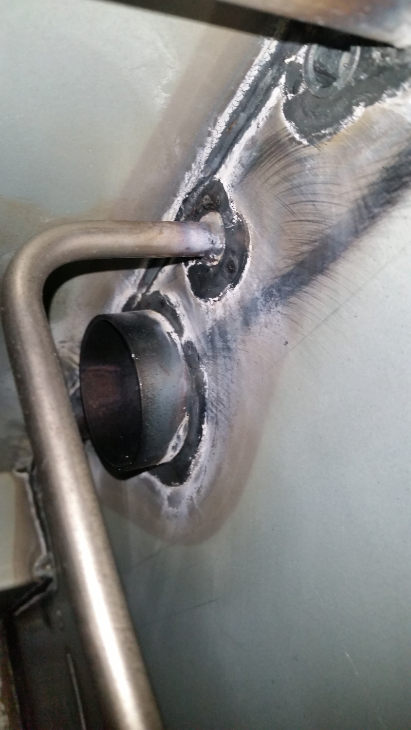
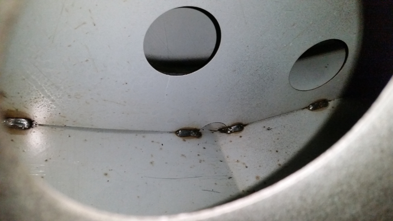
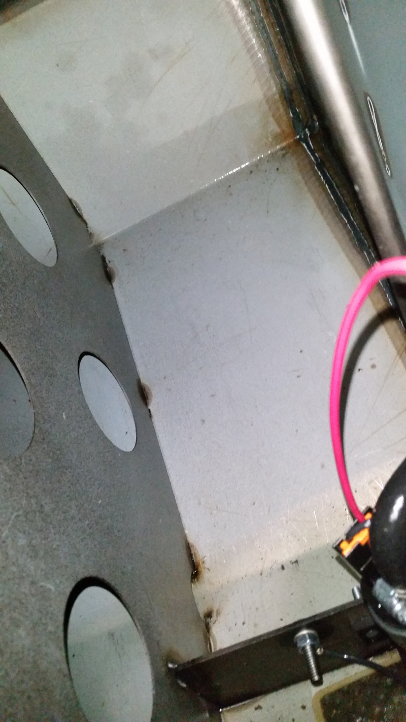
While waiting on a few items, I dropped the gas tank to see what the inside was coated with. Diesel apparently dissolves zinc finishes and redeposits them in the engine. Not good. Unfortunately there is some type of coating on the inside that looks very zinc-like. I will have to clean and seal the inside of this tank before proceeding. I found some other things I didn't like after removing the access cover. There was left over parts from assembly and weld slag floating around the bottom of the tank. Additionally the feed line is undersized and the return just shoots out the top of the tank, which can aerate the fuel. I will have to address these things as well.

47456746912_b5b6091072_o.jpg

47456746842_9bfa4eb5e1_o.jpg

47456746732_5c1527808a_o.jpg


Looks like pre-plated sheet metal. Note the return line is just a fitting welded to the side of the tank.
47509470631_4cbf4b1ffa_o.jpg


The baffles look decent
47456746452_24a601c9b9_o.jpg

40543573503_14c574f665_o.jpg
 
OP
OP
Digger556

Digger556

Sr. Member
Joined
Aug 8, 2013
Messages
793
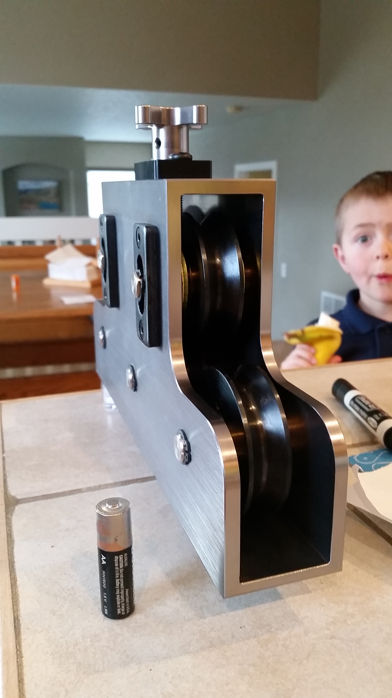
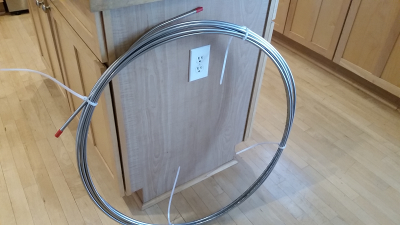
Since the fuel system is getting rearranged, I will have to run new hard lines. Wanting to do things a little nicer than last time, I'm upgrading to stainless for brakes and fuel. I decided to order a roll of tubing instead of straight pieces to eliminate any fittings along the frame rail.

This tube straightener is much bigger than I thought.
47509470461_8aa43d76eb_o.jpg


The roll of 3/8" tube is HUGE
47456746222_4b29282ee8_o.jpg


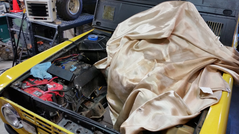
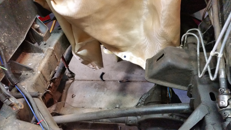
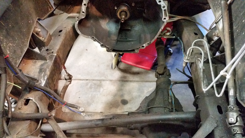
After some additional CAD modelling, it became clear the stock engine mounts will not work. They are too far rearward in the engine bay. I could get the engine mounted but the stock mounts prevent the Cummins starter from being removed without pulling the engine. So those have to go.
47509470321_f434ed5680_o.jpg

47456746042_d9bc39952a_o.jpg


Annnnnd gone.
47509470261_8e3b6eace5_o.jpg
 
Top