• Welcome to ClassicBroncos! - You are currently viewing the forums as a GUEST. To take advantage of all the site features, please take a moment to register. It's fast, simple and absolutely free. So please join our community today!
    If you have problems registering or can't log into your account, please contact Admin.

Pertronix Ignitor

mattyq17

Bronco Guru
Joined
Jul 11, 2007
Messages
1,597
So I was given a Pertronix Ignitor and flamethrower coil that I am going to use to replace the points in my 66 289. I did some searching on here last night and am still a bit confused. I have original wiring in my 66, there is the black wire from the distributor going to the neg. post on the coil, and a wire coming from the dash it looks like, it is loomed with other wires and heading that way but I didn't have time to trace it. This wire is going to the pos. post. Is this the resistor wire I have been reading about? This wire is not red/green stripe like I read about in others posts. I understand the new black wire goes to the neg. post but what about the new red wire? Do I tie it into the wire coming from the dash or just put both on the pos. post? We are getting rain here over the next 3 days so I wont be able to do any work since I have to work outside on it. Trying to get all my ducks in a row before I start. Thanks guys.
 

gr8scott

Contributor
Bronco Guru
Joined
Jul 1, 2011
Messages
1,828
Yes, that's probably the resistance wire. To verify, with the key on measure voltage from coil + to ground. You'll most likely
see 6-9 volts. The Pertronix needs full 12 volts, so the resistance wire will need to be bypassed with a new wire.
 

Boss Hugg

Contributor
Bronco Guru
Joined
Jun 8, 2010
Messages
2,142
I'd bet that since it's not r/g, someone has replaced it and there's not a resister in it.

Yes the red pertronix wire goes to positive side of coil.

And IIRC, the pertronix is supposed to work with resistance anyway...but someone should check me on that.
 

Eoth

Bronco Guru
Joined
Mar 10, 2004
Messages
1,677
Your original setup probably has three wires going to the positive post of the coil. One is the resistance wire, one goes back to the solenoid and the other goes to the distributor. As you know, you need full 12V all the time... The one going to the solenoid is good 12V but only for cranking, the other is never designed to give you full 12V (hence resistor).. You can either trace back the resistance wire (lots are originally pink but they wear out and need replaced so who knows what color now) or find another source. The black wire from your petronix goes to the negative terminal on the coil and the red wire from the petronix goes to the positive terminal. Just find a good source of 12V related to your "on ignition" and you are golden.
 
OP
OP
mattyq17

mattyq17

Bronco Guru
Joined
Jul 11, 2007
Messages
1,597
Thanks guys I will give it all a look as soon as the weather lets up, and let you know what I find.
 

B RON CO

Contributor
Bronco Guru
Joined
Jun 29, 2016
Messages
2,414
Loc.
Statesville, NC
Hi, X2. The original points and condenser ignition gets 12 v on crank and @ 7 v running, to save the points from burning out.
You can check the voltage at the coil with a mutimeter.
I would check Pertronix website to verify if they want 12 volts to the flamethrower coil.
I hooked mine up with 12 volts to the + coil, and attached the red ignitor wire to the + coil.
The black wire goes to the - coil, as does a tach wire if you have a tach.
You also have to set a gap on the 2 ignitor parts in the distributor. Check the Pertronix website for the correct gap.
I would reset the timing after installing your new ignition system.
Good luck
 
OP
OP
mattyq17

mattyq17

Bronco Guru
Joined
Jul 11, 2007
Messages
1,597
Okay so I had a quick few minutes before the rain started and I broke out the multimeter. With the key on I am getting 11.88 on the positive side of the coil. There is only one wire hooked up to the positive side and it’s black/brown stripe or appears to be. It then runs back to the firewall and goes into a 3 wire plug then inside the firewall. The other two wires look like they go to the oil sender and temp sender on the engine. Wish I would have had my phone to take some pictures. Oh and the blk/brwn wire turns into red/green at the 3 wire plug before it goes through the firewall. As soon as there is a break in the weather I will go take some pictures and look under the dash.

So since there is 12 volts already at the coil I “should” be able to just add the red pertronix wire to the positive side of the coil correct?

I read the instructions and that’s the way it shows to hook it up if not using a ballast resistor or resistor wire.
 

DirtDonk

Contributor
Bronco Guru
Joined
Nov 3, 2003
Messages
47,497
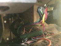
The coil + wire is either faded/color changed from the heat and age, or it was a different color to begin with for some reason.
It's also possible, as we found out here recently, that it is indeed the resistor wire. For as long as I have been working on Broncos, the resistor part of that circuit was always under the dash, between the ignition switch and the firewall. On the exterior side of the firewall it was just normal wire.
You can easily verify what yours is with an ohm-meter. Unplug the 3-wire connector, dosconnect it from the coil, and measure resistance.
One of the others will have to let you know what to look for, but basically if the resistance is very low, it's normal wire. If it's unusually high for such a short length of wire, it's a resistor wire.
Of course, there's another way and that's if you do happen to open up the tape a bit, it should actually say "do not cut or splice - resistor wire" right on it.

And yes, the other two are for the senders.

The firewall/chassis side of that 3-wire connector should also have a second wire molded right into where the Red w/green wire runs. This is your Brown wire from the starter relay that give the full 12v jolt while the starter is cranking.

You may read 11.88v now, but you need to put some kind of a load on that wire to get the correct voltage reading. It takes heat and time to build up it's full resistance.
So unless you add the load, reading the ohms is a more accurate way to determine wire type.

There is a position where the points are open or closed (closed I think?) where you have current traveling through the coil and heating the wire up. Someone else will have to tell you the correct orientation though. I'm not sure.
But that load plus a few minutes with the key on should also heat the circuit up enough to tell you if it's a resistor circuit.

----------------------------------------------

The Black wire of the Ignitor always goes to the negative side of the coil whether a resistor is used or not, or if a 12v coil is used or not.

The Red wire should have 12v supply for sure. But all the time, which is why you should still verify that it's not a resistor wire.
And yes, if you verify that it's a full 12v with no resistor in the line, then yes you can put the Red wire to the coil + along with the Red w/green (or Brown w/black) wire.

Paul
 

DirtDonk

Contributor
Bronco Guru
Joined
Nov 3, 2003
Messages
47,497
Oh, and x2 on the gap. I think it's .030" between the pickup and rotor/reluctor/thingy-with-tips to get the proper signal strength.
They usually include a small strip of plastic that's the correct thickness to use as a feeler gauge, but since you got yours second hand, it may not be there.

So definitely check their instructions to verify the gap setting.

Paul
 
OP
OP
mattyq17

mattyq17

Bronco Guru
Joined
Jul 11, 2007
Messages
1,597
Ok so I found the resistor wire under the dash at least I think I did see attached picture. Anyway I jumped the gun and hooked it all up with both the resistor wire and red wire from the pertronix on the positive side of the coil and it fired right up, faster than ever. Is leaving it like this going to do any damage?
 

Attachments

  • EB22B03C-DB86-463E-96FA-8A28563E742A.jpg
    EB22B03C-DB86-463E-96FA-8A28563E742A.jpg
    64 KB · Views: 36

DirtDonk

Contributor
Bronco Guru
Joined
Nov 3, 2003
Messages
47,497
Not necessarily. There has never been any kind of confirmation or consensus that low voltage harms the Ignitor module. Just that it doesn't always like it.

Normally, like you, most people just run it that way and move on.
But what I would do is set in your mind that if the engine ever starts running crappy or doesn't want to start easily in the morning, don't forget the low-voltage condition when you're hunting for likely culprits.

There are several here who've run the resistor wire and never had any issue. But there are likely more of us that actually have had issues when running the resistor.

Besides, it's hard to take something apart when it's working!

Paul
 

DirtDonk

Contributor
Bronco Guru
Joined
Nov 3, 2003
Messages
47,497
Oh, and yes that's your resistor wire. You have the replaceable version too. Nice.
It's standard wire as it exits the ignition switch, then at the green connector it becomes that pukey brown resistor wire color up to the firewall area somewhere.

Easy to bypass too though, if you someday have a wild hair.

Paul
 
Top