broncoitis
Bronco Guru
- Joined
- Jul 23, 2010
- Messages
- 4,449
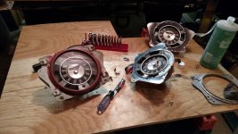
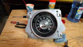
Good job Pete! Look like it came out nice! ;D


Nice job Pete..what a difference a blast and paint makes..Keep on it brother.
Looking good man !")
Gonna have to see a more recent pic to concur w/that statement ;D
Gonna have to see a more recent pic to concur w/that statement ;D

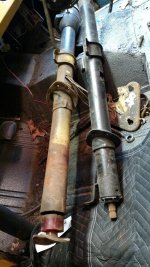
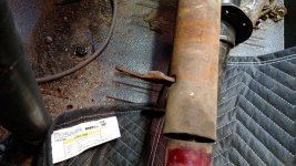
pete I don't have any pics, but I believe the 76', 77' 's have the collapsible shaft between the column and box???%)%)%)
Nice to see you working on it Pete..Keep it up.
On the column I believe that was a "one off" performance piece designed by Tony Hawk;D;D
So a headlight off the battery charger? Could I run a light off of a battery then as well?Pete,
Looks real good.
To test the ammeter, You should be able to just put a piece of wire through the alternator loop and using a batter charger, connect one lead and then just touch the other. The correct way would be to connect a low resistance load to it but even without you should be able to see the ammeter jump. This is assuming your charger has current fold back limiting which most if not all do. Don't do it with car battery as you can chance explosion. A good load could also be a spare headlight or Ignition resistor.
Pete,
Looks real good.
To test the ammeter, You should be able to just put a piece of wire through the alternator loop and using a batter charger, connect one lead and then just touch the other. The correct way would be to connect a low resistance load to it but even without you should be able to see the ammeter jump. This is assuming your charger has current fold back limiting which most if not all do. Don't do it with car battery as you can chance explosion. A good load could also be a spare headlight or Ignition resistor.