


Tech article by Ryan Flud
I searched high and low for a disc brake conversion kit for my ’73 Bronco. It seems virtually everybody sells the Chevy/Ford conversion, not to mention they charge about $800 +tax and shipping. I don’t mind using parts from other vehicles to make an upgrade or modification but I do want to try and stay with the same manufacturer. Through my research I continued to find articles briefly mentioning a conversion that used all Ford parts. Well I finally tracked down the year of the vehicles I needed to find. Had I known I was going to write this I would have taken more pictures at each step. The process must be is fairly easy to do if I was able to do it. Happy reading!
There is a catch to this conversion. Your tie-rod won’t fit correctly in the new steering knuckles. There are a couple of options to resolve this, I went with number two. I had actually purchased the tie-rod over conversion prior to doing anything with the disc brake conversion. The tie-rod over conversion moves your tie-rod up about 3” giving you less chance to catch it on something while wheelin’. It also helps negate the effects of a lift on your steering. So I’m told – it’s still sitting on my garage floor and I’m a long way from getting my machine on the road. Anyway, here are the two options as I see them.
Find a '78-'79 Bronco or a '73-'79 F150 (I used a '79 Bronco) and purchase everything from the knuckle out. I paid $250. This may be a bit high but they did all of the work to pull it off. You don't really need the rotor or caliper but I didn't know how cheap the caliper and hub/rotor assembly was when I bought these parts. Live and learn. The only reason you might want to go ahead and get everything from the knuckle out is so you get all of the hardware necessary for assembly. The vehicle I found didn't have the locking hubs but I had a new set of Warn's just waiting to be installed (Warn hubs not included in cost of conversion).
You may ask what is the "knuckle" and what is included when you get everything from the knuckle out? Well the knuckle, or steering knuckle, is the piece that has the upper and lower ball joints and is connected to the axle housing. There is an arm that sticks out towards the front of the vehicle; this is used to connect the tie-rod. All components of the wheel are ultimately connected to the vehicle via the knuckle. You'll understand that statement a bit better once you have started this conversion. See the picture in step #4 for the location of a steering knuckle.
As I understand it, the following items are included when you get everything from the knuckle out: Note: The items in bold are things that are "must have" items. The other items are items you can buy at your local parts store. You may be able to get the locking nut/lockring washer/adjusting nut and the caliper support key and spring from a parts store or maybe a Ford dealership. I got those items from the parts yard so I have no idea if you can get them elsewhere.
The rotor in most cases will need to be replaced (my needed it bad). The calipers should be rebuilt while you are there but I’ll leave that up to you. I could have cleaned and rebuilt the calipers I got from the ’79 Bronco but I just went ahead and bought new calipers (see my parts list for prices) to save time. The following is the list of parts I replaced: (all part numbers are from Autozone unless otherwise noted)
You may not need all of these parts, it will depend on the condition of your donor vehicle. My donor Bronco was missing the key retaining screw and I’ve seen other Bronco’s that just use a bolt and washer. All of these parts can be found at other places for more money if you feel better about a products quality because it costs more. Not that I don’t think “you get what you pay for” but in this case I think these are good quality parts. Once I had all the parts it was time for the fun stuff.
Note: All torque specs are either from the 1973 Ford Truck shop manuals or from a ’73-’79 Haynes Ford Pickup & Bronco manual, unless otherwise noted. You may want to double check the torque specs for your year.
Removal/Installation procedure
Note: Pay close attention to how things come apart. This will help you with some of the reassembly. Also almost every part should be labeled with left (L) or right (R). Left and right are as if you where sitting in the Bronco. Be sure that you check that you’re on the correct side of the Bronco for the part you have in your hand. One last thing before you move one with the conversion, the knuckle stud configuration is setup so you can’t put the correct part on incorrectly. This will become clear during the assembly of the parts. Take your time and have fun!
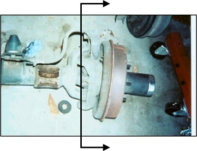
1. Remove the existing wheel locks, drums/brake assembly, spindle and knuckle. I already had my tie-rod removed so I won’t cover that piece. This removal of the drums, etc. was done by the shop that rebuilt my axles so I’ll only be able to detail the pieces I know. Besides, taking it apart is the easy part – right? Remove everything to the right of the line (on both sides). See the picture just before step two.
 2. Before installing any of the new parts from the ’79 Bronco I bead blasted them and then painted.
3. Then I used a ball joint press to remove the old ball joints from the ’79 Bronco knuckles and then install the new ball joints. You can borrow this tool from Autozone for free. It took a bit to figure out the best way to use it but once you get it working it’s easy. I wish I had a picture of this but I was so into it once it started working that I forgot all about the camera. The ball joint press I used looked like a big C-clamp with a large piece of all-thread. The best tip I can give you is put the C-clamp piece in a vise so it will hold everything for you will you use a ratchet/breaker-bar to press the ball joints in/out.

5. At this point I noticed the spindle bore seal on my axle was weathered and cracked. Autozone didn’t even know what it was even when I showed them the pictures below so I picked it up at the local Ford dealership. It was cheaper to buy the kit that comes with the spindle bore seal and a few other parts than to just buy the seal alone. I actually used one of the other pieces – a wheel bearing spacer. It’s a good thing because one of the original spacers didn’t make it back from the axle shop. Optional - Install the spindle bore seal and any of the other parts.

6. Install the brake backing plate. They are label left and right and should only go on at the correct angle. You’ll understand when you try to install them. See picture in step #8.
7. Install the caliper holder. Again they are labeled and should only go on one way. See picture in step #8.
8. Install the spindle. Tighten the nuts in a star pattern to make sure it goes in evenly. Torque the nuts to 30 - 40ft-lbs.

9. Before you can install the hub/rotor assembly you have to install the inner wheel bearing and seal (I think it’s called the inner wheel bearing seal) listed above, part #012035. If you get the same hub/rotor assembly as I did you’ll notice that both the inner and outer bearing races are already installed. So you will end up with four extra bearing races. Be sure and grease the bearings good before you install them. The inner wheel bearing seal is a bit of a pain to install. I covered the seal (metal and rubber) with a grease rag and lightly hit it with a hammer and a 6” socket extension until it was tightly seated.
10. Install the outer wheel bearing, don’t forget the grease!
11. Have the wheel bearing adjusting nut on hand for this part. Make sure the pin is sticking out of the adjusting nut; you’ll need it later in this step. Install the hub/rotor assembly and be careful not to knock the outer wheel bearing out. Push the hub/rotor into place and you should feel it seat. Install the wheel bearing adjusting nut and “Tighten the adjusting nut to 50 ft-lbs while rotating the wheel/hub assembly to seat the bearings. Back the adjusting nut of approximately 90 degrees” – quoted from the Haynes manual (’73 Ford Truck shop manuals say the same thing).
12. The lockring washer goes on next. It has a tongue that will only allow it to go on the spindle one way. This is trickery than you may think; the pin on the adjusting nut mentioned in #11 must go through one of the holes of the lockring. If it does not, remove the lockring and adjust the wheel bearing adjusting nut to allow the pin to go through the nearest hole in the lockring.
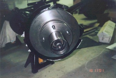
13. Install the wheel bearing lock nut and torque to 80-100 ft-lbs. Check this specification for you vehicle. The picture below is the installed hub/rotor.
14. Now the calipers. I’ve done disc brakes before but I must admit the Ford floating caliper seems weird. Install the anti-rattle clip in the bottom of the inner shoe and set the shoe in the caliper holder. Install the outer shoe in the caliper and place the caliper on the caliper holder. See the picture below.

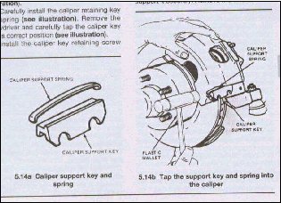
15. Take the caliper support spring and key and install them as described in the picture below. Install the key retaining screw (or a bolt and washer) and torque 12-20 ft-lbs.
And the final product…..

That’s pretty much it. I am still working on the brake lines; you can’t just buy ’79 lines because the lines are to long. I may just cut them down and put new ends on. We’ll see. I’ll update this document when I do. It should be in the next week or so. If you have any questions just send me an e-mail.
Ryan Flud
rflud@itprisms.com
This file also available in PDF format for Adobe Acrobat.
Update – 2.22.02 Since I wrote this article I have found the knuckles and spindles from the range of years listed above for much less than the $250 I paid. I have come to the conclusion that the place I purchased my parts from is extremely expensive. Keep an eye out for eBay auctions that are selling these parts and don't forget to check your local newspaper or the wrecking yards in your area. I have seen everything from the knuckle out as low as $40 (for both sides). Naturally this made me sick to my stomach. But the money is spent and the parts are installed. My suggestion – be patient and wait for a good deal not an amazing deal. If you wait for the amazing deal you will have drum brake for a very long time. I was able to use my original brake hard lines. New flex lines from the caliper to the hard lines are required. I purchased the lines from BC Broncos (www.bcbroncos.com). They are stainless steel braided brake lines. You can get regular rubber flex lines for much less, just make sure you get D.O.T (Department of Transportation) certified lines. Take a look at the picture below.

No matter which disc brake conversion you do (Chevy or Ford) you will want to install a proportioning valve. I have yet to do this; I'm still in the process of rebuilding my EB. I've seen proportioning valve range from $50 to $110 depending on the type of proportioning valve. The standard proportioning valve you will see on most trucks (and stock '76-'77 EB's) goes for about $90 to $110. I will be to this point soon and I will include the pictures and install tips in this article when I'm done.
I searched high and low for a disc brake conversion kit for my ’73 Bronco. It seems virtually everybody sells the Chevy/Ford conversion, not to mention they charge about $800 +tax and shipping. I don’t mind using parts from other vehicles to make an upgrade or modification but I do want to try and stay with the same manufacturer. Through my research I continued to find articles briefly mentioning a conversion that used all Ford parts. Well I finally tracked down the year of the vehicles I needed to find. Had I known I was going to write this I would have taken more pictures at each step. The process must be is fairly easy to do if I was able to do it. Happy reading!
There is a catch to this conversion. Your tie-rod won’t fit correctly in the new steering knuckles. There are a couple of options to resolve this, I went with number two. I had actually purchased the tie-rod over conversion prior to doing anything with the disc brake conversion. The tie-rod over conversion moves your tie-rod up about 3” giving you less chance to catch it on something while wheelin’. It also helps negate the effects of a lift on your steering. So I’m told – it’s still sitting on my garage floor and I’m a long way from getting my machine on the road. Anyway, here are the two options as I see them.
- BC Broncos has some adapter bushings that should allow you to use your stock tie-rod. Call Chuck @ (888) 304-2945 or visit their web site www.bcbroncos.com and go to steering.
- Purchase the tie-rod over conversion from BC Broncos.
Find a '78-'79 Bronco or a '73-'79 F150 (I used a '79 Bronco) and purchase everything from the knuckle out. I paid $250. This may be a bit high but they did all of the work to pull it off. You don't really need the rotor or caliper but I didn't know how cheap the caliper and hub/rotor assembly was when I bought these parts. Live and learn. The only reason you might want to go ahead and get everything from the knuckle out is so you get all of the hardware necessary for assembly. The vehicle I found didn't have the locking hubs but I had a new set of Warn's just waiting to be installed (Warn hubs not included in cost of conversion).
You may ask what is the "knuckle" and what is included when you get everything from the knuckle out? Well the knuckle, or steering knuckle, is the piece that has the upper and lower ball joints and is connected to the axle housing. There is an arm that sticks out towards the front of the vehicle; this is used to connect the tie-rod. All components of the wheel are ultimately connected to the vehicle via the knuckle. You'll understand that statement a bit better once you have started this conversion. See the picture in step #4 for the location of a steering knuckle.
As I understand it, the following items are included when you get everything from the knuckle out: Note: The items in bold are things that are "must have" items. The other items are items you can buy at your local parts store. You may be able to get the locking nut/lockring washer/adjusting nut and the caliper support key and spring from a parts store or maybe a Ford dealership. I got those items from the parts yard so I have no idea if you can get them elsewhere.
- The knuckle
- The brake backing plate
- The caliper holder (Haynes calls this the Anchor plate)
- The spindle
- Inner and outer wheel bearings and bearing races (inside the hub/rotor assembly. Definitely should be replaced)
- Hub/rotor assembly
- Wheel bearing locking nut, lockring washer (washer with several holes around the center hole), wheel bearing adjusting nut
- Caliper (maybe the brake lines)
- The caliper support key and spring
- Locking hubs (you'll probably want to replace these anyway so I would worry about this part)
- The knuckle
- The brake backing plate
- The caliper holder (Haynes calls this the Anchor plate)
- The spindle
- Wheel bearing locking nut, lockring washer (washer with several holes around the center hole), wheel bearing adjusting nut
- The caliper support key and spring
The rotor in most cases will need to be replaced (my needed it bad). The calipers should be rebuilt while you are there but I’ll leave that up to you. I could have cleaned and rebuilt the calipers I got from the ’79 Bronco but I just went ahead and bought new calipers (see my parts list for prices) to save time. The following is the list of parts I replaced: (all part numbers are from Autozone unless otherwise noted)
Item | Part # | Cost | Qty. | Total |
Ball Joints - Upper | 037366 | $17.99 | 2 | $35.98 |
Ball Joints - Lower | 201749 | $17.99 | 2 | $35.98 |
Caliper - Left (has FORD logo stamped on metal) | 208360 | $11.99 | 1 | $11.99 |
Caliper - Right (has FORD logo stamped on metal) | 208314 | $11.99 | 1 | $11.99 |
Wheel Bearing - Inner | 788737 | $12.99 | 2 | $25.98 |
Wheel Bearing - Outer | 788422 | $10.99 | 2 | $21.98 |
Seal (holds inner wheel bearing in place) | 012035 | $3.69 | 2 | $7.38 |
Rotor & Hub assembly (made in Canada) | 048859 | $31.99 | 2 | $63.98 |
Disc Brake Pads | MKD50V | $10.99 | 2 | $21.98 |
Bolt to hold retaining key & spring | ? | ? | 2 | ? |
Spindle Bore Seal Kit (from local Ford dealer) | SBK1 | $12.00 | 2 | $24.00 |
Anti-Rattle Clips | 704460 | $1.69 | 1 | $1.69 |
$251.94 |
You may not need all of these parts, it will depend on the condition of your donor vehicle. My donor Bronco was missing the key retaining screw and I’ve seen other Bronco’s that just use a bolt and washer. All of these parts can be found at other places for more money if you feel better about a products quality because it costs more. Not that I don’t think “you get what you pay for” but in this case I think these are good quality parts. Once I had all the parts it was time for the fun stuff.
Note: All torque specs are either from the 1973 Ford Truck shop manuals or from a ’73-’79 Haynes Ford Pickup & Bronco manual, unless otherwise noted. You may want to double check the torque specs for your year.
Removal/Installation procedure
Note: Pay close attention to how things come apart. This will help you with some of the reassembly. Also almost every part should be labeled with left (L) or right (R). Left and right are as if you where sitting in the Bronco. Be sure that you check that you’re on the correct side of the Bronco for the part you have in your hand. One last thing before you move one with the conversion, the knuckle stud configuration is setup so you can’t put the correct part on incorrectly. This will become clear during the assembly of the parts. Take your time and have fun!
1. Remove the existing wheel locks, drums/brake assembly, spindle and knuckle. I already had my tie-rod removed so I won’t cover that piece. This removal of the drums, etc. was done by the shop that rebuilt my axles so I’ll only be able to detail the pieces I know. Besides, taking it apart is the easy part – right? Remove everything to the right of the line (on both sides). See the picture just before step two.
- The removal of the wheel locks should be self explanatory.
- You will need a special socket to remove/install the wheal bearing locknut and the wheel bearing adjusting nut. I bought mine at Kragen. There is a lockring washer between these two nuts that has several holes in it. The wheel bearing adjusting nut has a small pin that goes into one of the holes of the retaining washer. You may or may not see this pin; it may have been pushed into the nut due to improper assembly. Once you have removed the wheel bearing adjusting nut you can use a small nail to push the pin out. This hardware should be interchangeable with the spindles from your donor vehicle and you can use them if you want.
- I believe the wheel drum and backing plate will come off as one piece but I may be wrong. The axle shop did this part (I asked them to leave it off since I was going to disc brakes. If it doesn't come off as one piece you'll have to remove the drum and figure it out, sorry.
- Remove the cotter pin from the upper ball joint and loosen the castle nut. I believe you can get a wrench on the lower ball joint's nut without removing your axle; you may have to turn the yoke on the axle housing to give you a bit more room. Then to remove the steering knuckle use a hammer (dead blow, 5 lb sledge, etc) and hit the castle nut on the upper ball joint. This will, eventually, cause the steering knuckle to comes loose. Finish removing the nuts on the upper and lower ball joint while holding the steering knuckle so it doesn't drop on the outer axle shaft.
3. Then I used a ball joint press to remove the old ball joints from the ’79 Bronco knuckles and then install the new ball joints. You can borrow this tool from Autozone for free. It took a bit to figure out the best way to use it but once you get it working it’s easy. I wish I had a picture of this but I was so into it once it started working that I forgot all about the camera. The ball joint press I used looked like a big C-clamp with a large piece of all-thread. The best tip I can give you is put the C-clamp piece in a vise so it will hold everything for you will you use a ratchet/breaker-bar to press the ball joints in/out.
- The upper ball joints come with a zerk fitting and a plug. The reason for this you need the zerk fitting to put grease in the ball joint but you can’t leave it in place because it will interfere with the axle as it turns. You must install the plug fitting after you put the grease in. The lower ball joint only comes with a zerk fitting.
7. Install the caliper holder. Again they are labeled and should only go on one way. See picture in step #8.
8. Install the spindle. Tighten the nuts in a star pattern to make sure it goes in evenly. Torque the nuts to 30 - 40ft-lbs.
10. Install the outer wheel bearing, don’t forget the grease!
11. Have the wheel bearing adjusting nut on hand for this part. Make sure the pin is sticking out of the adjusting nut; you’ll need it later in this step. Install the hub/rotor assembly and be careful not to knock the outer wheel bearing out. Push the hub/rotor into place and you should feel it seat. Install the wheel bearing adjusting nut and “Tighten the adjusting nut to 50 ft-lbs while rotating the wheel/hub assembly to seat the bearings. Back the adjusting nut of approximately 90 degrees” – quoted from the Haynes manual (’73 Ford Truck shop manuals say the same thing).
12. The lockring washer goes on next. It has a tongue that will only allow it to go on the spindle one way. This is trickery than you may think; the pin on the adjusting nut mentioned in #11 must go through one of the holes of the lockring. If it does not, remove the lockring and adjust the wheel bearing adjusting nut to allow the pin to go through the nearest hole in the lockring.
13. Install the wheel bearing lock nut and torque to 80-100 ft-lbs. Check this specification for you vehicle. The picture below is the installed hub/rotor.
Ryan Flud
rflud@itprisms.com
This file also available in PDF format for Adobe Acrobat.
Update – 2.22.02 Since I wrote this article I have found the knuckles and spindles from the range of years listed above for much less than the $250 I paid. I have come to the conclusion that the place I purchased my parts from is extremely expensive. Keep an eye out for eBay auctions that are selling these parts and don't forget to check your local newspaper or the wrecking yards in your area. I have seen everything from the knuckle out as low as $40 (for both sides). Naturally this made me sick to my stomach. But the money is spent and the parts are installed. My suggestion – be patient and wait for a good deal not an amazing deal. If you wait for the amazing deal you will have drum brake for a very long time. I was able to use my original brake hard lines. New flex lines from the caliper to the hard lines are required. I purchased the lines from BC Broncos (www.bcbroncos.com). They are stainless steel braided brake lines. You can get regular rubber flex lines for much less, just make sure you get D.O.T (Department of Transportation) certified lines. Take a look at the picture below.
