• Welcome to ClassicBroncos! - You are currently viewing the forums as a GUEST. To take advantage of all the site features, please take a moment to register. It's fast, simple and absolutely free. So please join our community today!
    If you have problems registering or can't log into your account, please contact Admin.

EFI Code(s) Question

70_Steve

Old Guy
Joined
Dec 13, 2002
Messages
8,317
So, I finally got the Bronco started after my EFI conversion. Bad TFI module hung me up most of the day yesterday. So I pulled codes this morning, and have quite a list, most of which seem explainable. They are: 51 22 53 54 35 67 81 82 85 84.

51 through 35 all have SIG RET (pin 46) in common, so I've got a starting point for troubleshooting those. 81 through 84 are the usual TAB/TAD/CANP/EGR that I will ignore.

The question I have, to start off, is about code 67. I would not have expected a code about the NSS. I've got a A9P EEC supposedly set up for a manual tranny. I didn't do the harness work, so I'm not sure exactly how it's wired. My understanding is that Pin 30 should be connected to SigRet (pin 46) also. Is this correct? Is this looking like another issue with the SigRet? I think I'm answering my own question...
 

Viperwolf1

Contributor
electron whisperer
Joined
Aug 23, 2007
Messages
24,322
Pin 30 to "S" terminal of starter solenoid with an A9P. Signal return with a manual ECM.
 
OP
OP
70_Steve

70_Steve

Old Guy
Joined
Dec 13, 2002
Messages
8,317
Pin 30 to "S" terminal of starter solenoid with an A9P. Signal return with a manual ECM.
OK, so I pulled the EEC and checked the wiring. Pin 30 really is connected to SegRet. What problems would this create? Could having pin 30 connected to SigRet be hosing up all the other signals that use SigRet? What happens (for now) if I just disconnect pin 30 from SigRet?
 

wpaeb

Sr. Member
Joined
Mar 19, 2005
Messages
429
Loc.
Clarion ,PA
OK, so I pulled the EEC and checked the wiring. Pin 30 really is connected to SegRet. What problems would this create? Could having pin 30 connected to SigRet be hosing up all the other signals that use SigRet? What happens (for now) if I just disconnect pin 30 from SigRet?

Check to see if pin 30 is also tied to the start circuit. If it is, applying 12v to it would of burnt the trace in pin 46, thus all those codes. If this happened it can be repaired.
 
OP
OP
70_Steve

70_Steve

Old Guy
Joined
Dec 13, 2002
Messages
8,317
Check to see if pin 30 is also tied to the start circuit. If it is, applying 12v to it would of burnt the trace in pin 46, thus all those codes. If this happened it can be repaired.
Pin 30 is not (thankfully) tied to the Start circuit.

OK, so I disconnected all the sensors that I'm getting codes for, and ran the KOEO test again. I still get the >4.6V codes for the two wire sensors. For the three-wire TPS and EVP, I'm now getting <.6 or .24 volt codes. And for the BP sensor, there is just an out-of-range code (not very helpful). So, in thinking about this, it really does seem like the SigRet is hosed up. I've check continuity in the harness at all connectors, and back to pin 46 on the EEC connector. I still have the SigRet connection at the STO/MIL connector, so, with all sensors still disconnected, I measured the voltage at the SigRet connection on the STO connector. 0.0 volts. Now, I connect the ECT sensor and measure the voltage at SigRet again. Now I get the full 4.67 volts. Hmmm.... It's beginning to look like my SigRet connection at the EEC is hosed.

wpaeb, do you have any specific info on repairing that trace on the board? I've repaired traces on circuit boards before. Not much fun...
 
OP
OP
70_Steve

70_Steve

Old Guy
Joined
Dec 13, 2002
Messages
8,317
Thank you wpaeb for the heads up on the burned track for pin 46. And thank you to Viperwolf1 for posting that link.

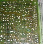
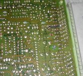
As it turns out, yes, the track for pin 46 SigRet, was burned, just like in the pics at Viperwolf1's link. I've just now finished repairing the track and put the EEC back together. One more check to make sure I don't get full 12 volts on SigRet, and I'll install the EEC and try again. I took some pics that I'll post later.

Edit: Success!!! Ran KOEO and the only codes are 81 82 84 85. The engine's still idleing a bit rough, but the throttle response, just sitting in the garage, is a huge improvement over the Carter AFB I was running!!!
 
Last edited:

wpaeb

Sr. Member
Joined
Mar 19, 2005
Messages
429
Loc.
Clarion ,PA
Glad I could point you in the general area. You were already on the right track. Now enjoy all the benefits of EFI!:cool:
 
OP
OP
70_Steve

70_Steve

Old Guy
Joined
Dec 13, 2002
Messages
8,317
So, to document this a little further, I took some before and after pics of the EEC board. To get into the EEC you will need a #15 and a #8 torx bit. The board is conformally coated (sticky plastic crap) so that will have to be removed before soldering. There are convenient places to solder to bridge the burned track. One end is the pin 46 connection it's self, and the other is a lead from a diode at the other end of the track. After cleaning the coating off both connection points, I just soldered a small wire between the two.
 

Attachments

  • pin 46 burnt track.jpg
    pin 46 burnt track.jpg
    117 KB · Views: 25
  • pin 46 fixed track.jpg
    pin 46 fixed track.jpg
    130.6 KB · Views: 30

Viperwolf1

Contributor
electron whisperer
Joined
Aug 23, 2007
Messages
24,322
That's really quick work on diagnosing, fixing and testing. Glad it's working.
 

Pedestrian

Bronco Missionary
Joined
Sep 10, 2008
Messages
2,299
Damn Steve, nice work!
I burned my ECU and just installed another. Now I think I will try to fix it for a trail spare
 
OP
OP
70_Steve

70_Steve

Old Guy
Joined
Dec 13, 2002
Messages
8,317
That's really quick work on diagnosing, fixing and testing. Glad it's working.
Thanks guys! It's amazing what I can get done when I have to! I WILL be at the Stampede on Friday!!!:cool:

[rant]I have to say that this project (EFI) has been the worst project I've done on the Bronco to date. Not that it was particularly technically difficult. But, maybe because there were so many steps to the install, it seemed like there was not one thing I tried to do where there was not a problem. Talk about quick work!!! I actually started this install over the Christmas holidays!!!:eek:

Still have a couple things to do/problems to resolve. There's still a bit of a rough idle. I'll try setting the idle speed per some instructions I've got to find in some thread again. I've got an Exploder throttle body that someone did the Lars mod to already, but there's a small hole in the throttle plate that looks like it was worked over. I wish there was a way to tell, with the engine running, when the IAB was at quarter-stroke.

Also, (to let you know how this project has gone), I still need to plug in the VSS. Sounds simple, huh. But, for some reason, with the speedometer cable installed in the rear of the VSS, the plug won't fit! So now I will loose an hour trying to determine the best way to install the plug. [/rant]

Coffee hasn't kicked in yet...
 
Top