• Welcome to ClassicBroncos! - You are currently viewing the forums as a GUEST. To take advantage of all the site features, please take a moment to register. It's fast, simple and absolutely free. So please join our community today!
    If you have problems registering or can't log into your account, please contact Admin.

D44 knuckle pre-load

DirtDonk

Contributor
Bronco Guru
Joined
Nov 3, 2003
Messages
47,483
Mike's torque on the upper sleeve is probably gleaned from years of experience, but the "by the book" torque is actually 40lbs on the adjusting sleeve.
The issue I mentioned earlier with the sleeve coming out the bottom is why I also ended up going with less torque than specified in the book, because it was no longer working. The is possibly what he's adjusting for as well. Either that, or he's got a service manual that shows a different torque setting.
But did you also notice that he stated that after the final torquing of the upper nut, the pull on the scale got lighter? This is why the books specify checking the pull force AFTER the assembly is finalized.
But his method of checking first is probably even better, and lets you fine tune things based on your experiences with your particular front axle. Just as long as you measure your pull strength after the final torque of the upper nut to verify that it's "less than 26lbs" of force.

If someone has a factory manual handy, it would be nice to confirm. Since the Chilton's paperbacks were often riddled with small mistakes, and the Hayne's version that I have does not even address ball-joints, it would be nice to have another reference. Maybe the 40lb rating on the sleeve from the Chilton's is incorrect.

Paul
 

mpboxer

Contributor
Sr. Member
Joined
Dec 12, 2014
Messages
786
Loc.
Queen Creek, AZ
Mike's torque on the upper sleeve is probably gleaned from years of experience, but the "by the book" torque is actually 40lbs on the adjusting sleeve.
The issue I mentioned earlier with the sleeve coming out the bottom is why I also ended up going with less torque than specified in the book, because it was no longer working. The is possibly what he's adjusting for as well. Either that, or he's got a service manual that shows a different torque setting.
But did you also notice that he stated that after the final torquing of the upper nut, the pull on the scale got lighter? This is why the books specify checking the pull force AFTER the assembly is finalized.
But his method of checking first is probably even better, and lets you fine tune things based on your experiences with your particular front axle. Just as long as you measure your pull strength after the final torque of the upper nut to verify that it's "less than 26lbs" of force.

If someone has a factory manual handy, it would be nice to confirm. Since the Chilton's paperbacks were often riddled with small mistakes, and the Hayne's version that I have does not even address ball-joints, it would be nice to have another reference. Maybe the 40lb rating on the sleeve from the Chilton's is incorrect.

Paul
My driver side actually did loosen up after tightening the castle nut and wasn’t concerned because he explained that.

Wonder if the 40lbs on the adjusting sleeve actually prevents the increased pull after tightening the castle nut? I’ll let you know how it goes.
 

mpboxer

Contributor
Sr. Member
Joined
Dec 12, 2014
Messages
786
Loc.
Queen Creek, AZ
Well, I completed the installation. Torqued bottom ball joint nut to 70, castle nut to 100.

What about the sleeve what was that torqued to??

this is what I do with good results {just did 2 sets last Wednsday}

sleeve partia;ly installed in knuckle
torque lower 80FtLbs.
torque sleeve to 40FtLbs, 45 if you want a little less effort when done.....but when doing this only torque once and stop don't go back for a second click;;;
torque upper ball joint nut to 80FTLbs then tighten to line up for cotter pin...

It is possible to damage the ball joint when pressing into knuckle if someone is using the incorrect install cup...been there before on a f350
EPB72 is dead on here.

I tried various looser positions with adjustment sleeve…no luck. I think it is counter intuitive but the sleeve actually needs to be tighter on the tapered ball joint stud. This may prevent the castle nut from sucking it up too much.

Torqued sleeve to 40lbs. Tightened castle nut to 80lbs and then added a little more (which is probably right at 100lbs now) to insert cotter pin. Knuckle pull at 12lbs which I’m good with.

Thanks all for the help and hope this thread helps out others. Thanks to the OP for letting me bomb it and share my experiences.
 
OP
OP
L

levib1

Newbie
Joined
Dec 7, 2016
Messages
55
Just to bring you up to speed on my experience...

Driver side perfect.

Pax side nearly locked up after complete assembly. Once disassembled and knuckle removed, I jammed two nuts on the lower ball joint and did some experimenting. Ball joint extremely stiff and difficult to spin, therefore, swapping it out.

I am replacing the bottom ball joint tomorrow and will reassemble. Will report then.

Also, on another note, the upper ball joint Zerk hole is not tapped (either side.) Went to auto-parts store and looked at some others and they were the same! Ball joint includes what appears to be a threaded Zerk fitting???? I'm confused. Am I supposed to 'force thread' the Zerk in? The bottom ball joint threaded and the Zerk threads in fine.

Thanks all
 

mpboxer

Contributor
Sr. Member
Joined
Dec 12, 2014
Messages
786
Loc.
Queen Creek, AZ
Just to bring you up to speed on my experience...

Driver side perfect.

Pax side nearly locked up after complete assembly. Once disassembled and knuckle removed, I jammed two nuts on the lower ball joint and did some experimenting. Ball joint extremely stiff and difficult to spin, therefore, swapping it out.

I am replacing the bottom ball joint tomorrow and will reassemble. Will report then.

Also, on another note, the upper ball joint Zerk hole is not tapped (either side.) Went to auto-parts store and looked at some others and they were the same! Ball joint includes what appears to be a threaded Zerk fitting???? I'm confused. Am I supposed to 'force thread' the Zerk in? The bottom ball joint threaded and the Zerk threads in fine.

Thanks all
I noticed that too with the zerk fittings on the top ball joints. I figured they were self tappers, so I just threaded them in.
 

DirtDonk

Contributor
Bronco Guru
Joined
Nov 3, 2003
Messages
47,483
Correct. Pretty sure they've been this way, at least with some brands for decades. If not from the beginning.
I've always threaded them in to the blank holes.

Paul
 
OP
OP
L

levib1

Newbie
Joined
Dec 7, 2016
Messages
55
Success!

Replaced bottom ball joint (actually replaced both sides with Moog ball joints, as the bottom ball joints with the kit were not Moog, though the top were).

Torqued bottom nut to 70, screwed sleeve in until about 25 lbs of pull on the knuckle to move it.

Tightened castle nut to 100, or slightly over to get cotter pin to line up.

Now both knuckles have settled into about 20-22 lbs of pull.

As far as the Zerks - just self tappers - screwed them in. That had me confused for a bit.

Now onto axles, spindles and hubs...
 

mpboxer

Contributor
Sr. Member
Joined
Dec 12, 2014
Messages
786
Loc.
Queen Creek, AZ
Success!

Replaced bottom ball joint (actually replaced both sides with Moog ball joints, as the bottom ball joints with the kit were not Moog, though the top were).

Torqued bottom nut to 70, screwed sleeve in until about 25 lbs of pull on the knuckle to move it.

Tightened castle nut to 100, or slightly over to get cotter pin to line up.

Now both knuckles have settled into about 20-22 lbs of pull.

As far as the Zerks - just self tappers - screwed them in. That had me confused for a bit.

Now onto axles, spindles and hubs...
Good stuff! Honestly I think the hardest part is over. I say that and I'm literally trying to figure out why I don't have any brake pedal. I bench bled the master cylinder. I think I need to bleed the system more (fingers crossed). Keep us updated!
 
OP
OP
L

levib1

Newbie
Joined
Dec 7, 2016
Messages
55
Any input on the rest of the assembly? Looking for an exploded diagram for the spindle/axle/hub interface.

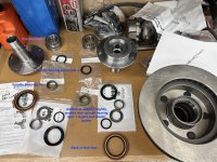
I have a number of parts that came with the kit.

2 large bearings which i'm pretty certain one goes each side of the hub to ride on the spindle. And also a large seal which goes on the back of the hub.

Then there's the spindle bearings and spindle bearing small seals? I'm assuming the spindle bearing gets pressed into the back of the spindle, but where does the spindle bearing small seal go?

In the foreground of the pic, there is another spindle bearing (duplicate I think), but also more seals (1 slightly smaller than the spindle bearing small seal and 1 considerably larger)

Couple questions:

1. Appears that the race for bearings pressed into hub. Therefore, do I only use the bearing, not the race of the big hub bearings?

2. When pressing the large seal into the hub, do I put any sealant on the seal? Same question for any other seals...

3. Not certain as to the assembly order of parts. Any info would be greatly appreciated. I am clear on the outer hub assembly, it's just everything else that is in the picture below.

Thanks again!

IMG_1127.jpeg and a gray plastic spacer
 

mpboxer

Contributor
Sr. Member
Joined
Dec 12, 2014
Messages
786
Loc.
Queen Creek, AZ
Any input on the rest of the assembly? Looking for an exploded diagram for the spindle/axle/hub interface.

I have a number of parts that came with the kit.

2 large bearings which i'm pretty certain one goes each side of the hub to ride on the spindle. And also a large seal which goes on the back of the hub.

Then there's the spindle bearings and spindle bearing small seals? I'm assuming the spindle bearing gets pressed into the back of the spindle, but where does the spindle bearing small seal go?

In the foreground of the pic, there is another spindle bearing (duplicate I think), but also more seals (1 slightly smaller than the spindle bearing small seal and 1 considerably larger)

Couple questions:

1. Appears that the race for bearings pressed into hub. Therefore, do I only use the bearing, not the race of the big hub bearings?

2. When pressing the large seal into the hub, do I put any sealant on the seal? Same question for any other seals...

3. Not certain as to the assembly order of parts. Any info would be greatly appreciated. I am clear on the outer hub assembly, it's just everything else that is in the picture below.

Thanks again!

View attachment 874946 and a gray plastic spacer
I used these as a valuable resource. I’ll try and respond to your specific questions tonight.

Unbox


Booster, Bracket, Prop Valve


Install


Knuckle Install


Wheel Bearing Tech / Hub Sequence


Master Cylinder


https://youtu.be/SdF5COv0qGI


Bleeding Master Cylinder


https://youtu.be/flefiok8s7A
 
OP
OP
L

levib1

Newbie
Joined
Dec 7, 2016
Messages
55
I appreciate the videos. I've watched them and still had some questions on the various parts.

Think I've got some of it handled.

Not sure on how much grease to use in various places? Should all voids be grease in the spindle and hub?

Thanks
 

mpboxer

Contributor
Sr. Member
Joined
Dec 12, 2014
Messages
786
Loc.
Queen Creek, AZ
I appreciate the videos. I've watched them and still had some questions on the various parts.

Think I've got some of it handled.

Not sure on how much grease to use in various places? Should all voids be grease in the spindle and hub?

Thanks
Any input on the rest of the assembly? Looking for an exploded diagram for the spindle/axle/hub interface.

I have a number of parts that came with the kit.

2 large bearings which i'm pretty certain one goes each side of the hub to ride on the spindle. And also a large seal which goes on the back of the hub.

Then there's the spindle bearings and spindle bearing small seals? I'm assuming the spindle bearing gets pressed into the back of the spindle, but where does the spindle bearing small seal go?

In the foreground of the pic, there is another spindle bearing (duplicate I think), but also more seals (1 slightly smaller than the spindle bearing small seal and 1 considerably larger)

Couple questions:

1. Appears that the race for bearings pressed into hub. Therefore, do I only use the bearing, not the race of the big hub bearings?

2. When pressing the large seal into the hub, do I put any sealant on the seal? Same question for any other seals...

3. Not certain as to the assembly order of parts. Any info would be greatly appreciated. I am clear on the outer hub assembly, it's just everything else that is in the picture below.

Thanks again!

View attachment 874946 and a gray plastic spacer
It looks like you got double spindle bearings and black o-rings on accident. Make sure you smack the spindle bearing in enough for the little black o-ring to ride in. That o-ring is tapered, I believe that will go to the plastic bushing with the matching taper on the axle. The larger black seal with two flanges and v-type groove will go on the axle, then bushing, then rubber o-ring. I didn’t see a Diff video for that.


  1. Yes just use bearings, races already installed in hubs. Large bearing for inner.


  1. I did not use any sealant as it is just keeping grease in and water/debris out (not sure if that is the correct way). I guess I’m thinking of a pinion seal where I smear a little RTV on it because it’s gear oil.


  1. Caliper bracket (Marked L and R and make sure retaining clip hole is down) will go first then axle (with seals attached, then spindle. Make sure you use anti seize on all the mating surfaces.


I had to really push my axles out from inside the knuckle to get the first c-clip on the axle for my factory hubs.
 

mpboxer

Contributor
Sr. Member
Joined
Dec 12, 2014
Messages
786
Loc.
Queen Creek, AZ
I appreciate the videos. I've watched them and still had some questions on the various parts.

Think I've got some of it handled.

Not sure on how much grease to use in various places? Should all voids be grease in the spindle and hub?

Thanks
I greased everything I could. Axle, spindle, hub parts and obviously packed all bearings.
 
OP
OP
L

levib1

Newbie
Joined
Dec 7, 2016
Messages
55
Thanks!

I've set the spindle bearings in and then put the seal in.

I don't understand "That o-ring is tapered, I believe that will go to the plastic bushing with the matching taper on the axle." What plastic bushing are you talking about?

Also, the large black seal that goes on the axle - does it get grease anywhere? Probably dumb question...


Thanks again
 

mpboxer

Contributor
Sr. Member
Joined
Dec 12, 2014
Messages
786
Loc.
Queen Creek, AZ
Thanks!

I've set the spindle bearings in and then put the seal in.

I don't understand "That o-ring is tapered, I believe that will go to the plastic bushing with the matching taper on the axle." What plastic bushing are you talking about?

Also, the large black seal that goes on the axle - does it get grease anywhere? Probably dumb question...


Thanks again
You have it labeled as “plastic spacer” in your picture. Is the spacer flat on both sides or is one side concave? If flat on both sides the black o-ring is probably flat too.

Not sure about grease on that seal. I don’t think a little would hurt.
 
OP
OP
L

levib1

Newbie
Joined
Dec 7, 2016
Messages
55
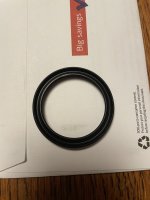
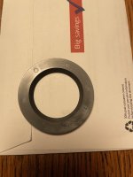
'Plastic spacer' flat on one side, other side is flat except for the inner 1/8", it is concave. See pic of concave side. The ID of the gray 'plastic spacer' is the OD of the inner portion of the outer axle, just outboard of where the large black o-ring fits on axle.

The only other part, besides the 'plastic spacer' is the other black seal, slightly larger than the spindle seal. I think it might be extra? It looks just like the spindle seal, but is slightly larger.

See photos of those two pieces.

IMG_1129.jpeg IMG_1128.jpeg
 
OP
OP
L

levib1

Newbie
Joined
Dec 7, 2016
Messages
55
Been in and out of the shop all night. One more question.

I've been reading Dana 44 manual - found link somewhere on this forum.

The plastic thrust washer goes on axle before spindle. Chamfered side towards inner axle.

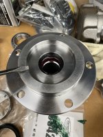
There is discussion of a grease seal on the spindle? Does anyone know if that applies to this Duff Monster Disc Kit? Or is it just the small spindle seal that goes over spindle bearing?

Attached is a pic pointing to where a seal may go?

Also, wondering if I seated the spindle bearing too far?

Sorry for all the disjointed questions. Maybe at the end I'll organize into one clean post - could be useful for others?

Thanks all
IMG_1130.jpeg
 

mpboxer

Contributor
Sr. Member
Joined
Dec 12, 2014
Messages
786
Loc.
Queen Creek, AZ
'Plastic spacer' flat on one side, other side is flat except for the inner 1/8", it is concave. See pic of concave side. The ID of the gray 'plastic spacer' is the OD of the inner portion of the outer axle, just outboard of where the large black o-ring fits on axle.

The only other part, besides the 'plastic spacer' is the other black seal, slightly larger than the spindle seal. I think it might be extra? It looks just like the spindle seal, but is slightly larger.

See photos of those two pieces.

View attachment 874952 View attachment 874953
I’m pretty sure the concave part of that spacer faces out, but don’t know why. Maybe someone else knows? I thought the black o-ring fit in there but it doesn’t.
 
Top