• Welcome to ClassicBroncos! - You are currently viewing the forums as a GUEST. To take advantage of all the site features, please take a moment to register. It's fast, simple and absolutely free. So please join our community today!
    If you have problems registering or can't log into your account, please contact Admin.

Power to horn button but none to horn

Oldtimer

Contributor
Jr. Member with Sr. moments
Joined
Feb 4, 2005
Messages
859
Loc.
Sunnyvale, CA
Yes, thats how it should work.

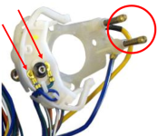
I have been talking about contacts in the circle.
I think you are talking about the contacts the arrows point at.
2022-11-24_195932.png
 
OP
OP
Y

YNOTBOB2007

Full Member
Joined
Oct 2, 2007
Messages
207
the contacts I were jumping are neither of those.....they are the 2 contacts on the metal plate, located at 4:00 and 8:00. You have to remove the metal plate (held in place by the big center nut) to get to your pic. But now I will try jumping the two in the red circle. Thanks for posting the pic....that's exactly what I have under the metal plate
 

DirtDonk

Contributor
Bronco Guru
Joined
Nov 3, 2003
Messages
47,490
OK...I found the wires exiting the column....mine has different conectors (1969)....one blue plastic onnector per wire. The connectors do not separate as far as I can tell.
Someone cut off the original connectors and used permanent, crimp connectors. Workable, but not serviceable.
If you ever need to change your turn signal switch (which you might have to soon) you will have to cut the wires at the blue connectors.
All look good.
Not good enough. Yes, they might be fine. But no, they might also have a corrosion or lose connections inside where you can’t see them. Have you at least tugged on the wires at each one to make sure they are still tight?
I can follow the blue/yellow stripe wire going from the connector into the back of the fuse box.
Most of the wires in the vehicle go to the back of the fuse panel, or at least appear to, because the firewall connectors are right there on the other side.
Those firewall connectors can be separated in the engine compartment, and you can inspect and test and clean and lube some of the circuits that way.
My user manual (original) shows the horn wiring is on the same circuit as the stop lights, taillights and license plate light...which is a 15 amp circuit breaker "intergral with the lighting switch". I am assuming "integral to the lighting switch" means there is no actual glass fuse?
Correct all those circuits you mentioned are powered by the wire powering the headlight switch. These are circuits that are constant hot and do not need the key in the ignition switch to work.
They are also fairly critical, so are protected by a self resetting circuit breaker, instead of a fuse that can blow.
I’m not sure which of these circuits are simply powered by the switch, and which are actually protected through the circuit breaker. Maybe all of them, but I’m not sure.
Whenever I have experienced a bad headlight switch, I have not checked to see if the brake lights and horn were still working.
And even if there is one and it's bad, the lights wouldn't work.
Correct. The headlights would not work. In fact, that’s one of the hallmarks of a failing or overloaded, headlight switch. The headlights switching off and back on repeatedly.
 

DirtDonk

Contributor
Bronco Guru
Joined
Nov 3, 2003
Messages
47,490
the contacts I were jumping are neither of those.....they are the 2 contacts on the metal plate, located at 4:00 and 8:00. You have to remove the metal plate (held in place by the big center nut) to get to your pic. But now I will try jumping the two in the red circle. Thanks for posting the pic....that's exactly what I have under the metal plate
To get to those, you actually have to remove the steering wheel itself. The horn button mechanism simply connects those two together.
If jumping those two results in the horn honking, then the problem is in your horn button. Or perhaps in the two copper traces on the back of the steering wheel that come in contact with those.

Whenever you service the turn signal switch or remove the steering wheel for any reason it’s not a bad idea to use dielectric grease on the contacts.
They can wear every time the wheel turns. Just as they do every time you honk the horn.
That’s where a relay comes in handy by reducing the wear and tear from using the horn.
 
OP
OP
Y

YNOTBOB2007

Full Member
Joined
Oct 2, 2007
Messages
207
To get to those, you actually have to remove the steering wheel itself. The horn button mechanism simply connects those two together.
If jumping those two results in the horn honking, then the problem is in your horn button. Or perhaps in the two copper traces on the back of the steering wheel that come in contact with those.

Whenever you service the turn signal switch or remove the steering wheel for any reason it’s not a bad idea to use dielectric grease on the contacts.
They can wear every time the wheel turns. Just as they do every time you honk the horn.
That’s where a relay comes in handy by reducing the wear and tear from using the horn.
awesome...problem fixed. Once I realized I was jumping the wrong contacts, I removed the wheel and jumped the right ones....sure enough the horn worked. I read an old post of someona also getting power to both contacts and I bet he was testing the wrong ones too. I added some dielectric to the contacts and the metal ring, reinstalled the horn button....all works now. When my turn signals stop working I guess I'll have to cut the wires like you say. It's not a daily driver...mostly seasonal mountain roads. If I decide to open the engine side firewall connectors, is it ok to add dielectric grease to the connectors? Usually I just spray electic cleaner....but maybe the grease is better? If you can point the way in doing a horn relay, I'll add it to my list. Thanks very much!
 

DirtDonk

Contributor
Bronco Guru
Joined
Nov 3, 2003
Messages
47,490
Great! Congratulations!
I always say it’s nice to have a working horn.
Probably just because it’s nice to have anything electrical working on a bronco!

I’ll give you a quick rundown on the relay install in a bit.
 

DirtDonk

Contributor
Bronco Guru
Joined
Nov 3, 2003
Messages
47,490
Ok, a bit later... :rolleyes:
Adding a standard relay to the original non-relay type horn circuits (pre-'74) on a Bronco is relatively straightforward.
Get yourself a 30a or 40a rated (most common) cube relay generally known as a "Bosch Type" or "Hella Type" relay. Some will have just an 87 terminal pin, and some will have both an 87 and an 87A terminal. That's ok, but you will only use the 87 terminal. The 87A terminal is hot only when the switch is off, so you definitely don't want that!

You can literally mount this relay anywhere you want, but it's probably easiest for wiring if you put it near the horn itself. Driver's side within easy reach of the existing horn wire.
One less step in the wiring process this way.

Before you mount the new relay, unplug the wire from the horn and connect it to the #86 pin on the relay. This will give you your mounting location, perhaps right on the wheel well brace that the horn is mounted to, based on the length of available original wire from the harness.
If you don't like this location, or the limitations of the length of the existing wire, now's the time to decide where you really want to mount the relay and then you can splice the needed length of wire to the original Ford horn wire.
Once this mounting process is over, here's where all new wiring starts. Might as well use 12 to 14 gauge wire for this project. A 16-22 gauge wire is fine for 85 and 86, but 30 and 87 need heavier wire. A 14 is probably fine for this, and a 12 is probably a bit overkill.
Up to you...

New wires to create are:
1. Pin #30 - Positive/Battery: A constant hot wire from pin 30 to a constant voltage source such as the battery side of the starter relay.
2. Pin #85 - Negative/Ground: A ground wire for the relay circuit only. Can be as short or as long as you need it to be to get from pin #85 to a well grounded bit of metal.
3. Pin #86 - Switched/Positive 12v: This is where your original horn wire is connected to act as a 12v switched source to energize the relay.
4. Pin #87 - Power to Horn: A wire from pin #87 runs directly to the horn where your old horn wire used to connect.
Done...

All you are doing is converting this so that your horn button now activates a relay (basically just a remote switch) which then powers the horn. Taking power over a shorter distance from the battery to the horn over a larger wire with fewer connections will help ensure that the horn receives full battery voltage any time it's needed. And it also reduces the current that passes through the original horn contacts up at the steering wheel so they no longer carry the full load of the horn. Just the milivolts it takes to energize the relay instead.

Clear as mud? Get the parts and stare at the horn for a minute and it'll all make sense.

Paul
 
Top