I saw this today in another thread. It looks like they got the problem solved but I wanted to make a specific thread about this issue that hopefully will help someone else, I've seen it many times.
Unless you are an old Mopar guy the speedometer gear and housing in an Atlas transfer case or HD Dana 20 output can be problematic to get the speedometer to function. It is really simple in design but not clear when no one tells you how to get it to work correctly.
I'll start with the design, which is really simple when explained how and why, it was copied not so much because the Advance Adapters parts were designed to copy a jeep, it goes much further back than that to Mopar/Dodge/Chrysler/Plymouth. When they developed the Torque Flight series of transmissions in the late 1950's they developed a speedometer drive that could accommodate a very large swing of gear ratios and tire sizes with a single drive gear on the output. To do this, it required that the driven gears be able to be different diameters to accommodate the range of teeth available. The tooth count has a wide range from 26-45 teeth. This design was carried all the way through to the mid 2000's when they were replaced with a speed sensor.
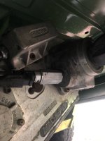
Now on to "why won't my speedometer work?". It is simple really, to accommodate the diameters of the gears they made the driven gear holder eccentric; it rotates to accommodate the different diameters of the driven gear, moving the axis of the driven gear closer or further away from the drive gear as the housing is rotated. This picture isn't super clear but you can see that it is eccentric. You can also read the numbers on the gear holder, the dot next to the numbers needs to be pointed at the 6 o'clock position for the tooth count range that your gear has. Do that and install the clamp and it will drive your speedometer or VSS adapter just like it is supposed to. The trouble arises when a 33-tooth gear is installed in the 39-45 tooth position and not in the 32-38 tooth position, the gears are not meshing together. I find it helpful to use a small screwdriver in the square end to turn the driven gear while in stalling so the gears mesh together and ease that installation.

Now if your speedometer is not correct, the tooth count needs to be more to make the speedometer read slower and less to read faster. So if your speedometer reads 66mph when you are traveling 60mph and you have a 33 tooth gear, going to a 36 tooth should get you within 2% of 60mph. Same if it reads 55 when traveling 60mph, going from a 33 tooth to a 30 tooth should get within 2%. FYI most OEM speedometers are only accurate within 5% so getting within 2% is very good.
Happy speedometer gear installing")
Unless you are an old Mopar guy the speedometer gear and housing in an Atlas transfer case or HD Dana 20 output can be problematic to get the speedometer to function. It is really simple in design but not clear when no one tells you how to get it to work correctly.
I'll start with the design, which is really simple when explained how and why, it was copied not so much because the Advance Adapters parts were designed to copy a jeep, it goes much further back than that to Mopar/Dodge/Chrysler/Plymouth. When they developed the Torque Flight series of transmissions in the late 1950's they developed a speedometer drive that could accommodate a very large swing of gear ratios and tire sizes with a single drive gear on the output. To do this, it required that the driven gears be able to be different diameters to accommodate the range of teeth available. The tooth count has a wide range from 26-45 teeth. This design was carried all the way through to the mid 2000's when they were replaced with a speed sensor.
Now on to "why won't my speedometer work?". It is simple really, to accommodate the diameters of the gears they made the driven gear holder eccentric; it rotates to accommodate the different diameters of the driven gear, moving the axis of the driven gear closer or further away from the drive gear as the housing is rotated. This picture isn't super clear but you can see that it is eccentric. You can also read the numbers on the gear holder, the dot next to the numbers needs to be pointed at the 6 o'clock position for the tooth count range that your gear has. Do that and install the clamp and it will drive your speedometer or VSS adapter just like it is supposed to. The trouble arises when a 33-tooth gear is installed in the 39-45 tooth position and not in the 32-38 tooth position, the gears are not meshing together. I find it helpful to use a small screwdriver in the square end to turn the driven gear while in stalling so the gears mesh together and ease that installation.
Now if your speedometer is not correct, the tooth count needs to be more to make the speedometer read slower and less to read faster. So if your speedometer reads 66mph when you are traveling 60mph and you have a 33 tooth gear, going to a 36 tooth should get you within 2% of 60mph. Same if it reads 55 when traveling 60mph, going from a 33 tooth to a 30 tooth should get within 2%. FYI most OEM speedometers are only accurate within 5% so getting within 2% is very good.
Happy speedometer gear installing