


Basic Vehicle Electrical Diagnosis
Tech article by admin and filed under ElectricalTech article by Gilbert Leonard (bert)
The purpose of this article is to help provide a little background information to troubleshoot most basic electrical problems. The information contained is from personal experience in the automotive field and is not to be understood as absolute or the only solution to finding electrical problems. Some of the hints I suggest you will not find in any book and, may not apply to your particular situation. I will assume you have some basic background knowledge but I will try to make my explanations as clear as possible.Diagnosing electrical systems can seem overwhelming, but if you break it down into smaller pieces it will be easier. Many people just go out and replace things until they end up replacing the faulty part. While there are times this is the only way, (substitute a known good part), it is costly and frustrating. Invest your money instead into a Service Manual with a wiring diagram and a quality Volt-Ohm meter.
Basic Tools and Caution:
The most helpful tool you can have is quality high impedance Volt-Ohm meter (low impedance Voltmeters will give misleading information, and can damage sensitive electronics). Two test lights, one the run of the mill test light found in any parts store or tool truck. The second one is homemade from a headlight (fig. 1). I prefer to use the small replaceable ones found in composite headlamp assemblies. Lastly, a couple of good jumper wires with alligator clips on both ends. A quality wiring diagram will speed the diagnosis process tremendously. Whenever making electrical repairs or doing major repair work, ALWAYS DISCONNECT THE BATTERY. Batteries can and do EXPLODE! Avoid creating sparks near the battery by turning all accessories and the key off before undoing the cables. The negative side should be the first undone and the last reconnected. Pay attention to where your test leads are; don’t let them get in the fan while the engine is running.
Consider the electrical system on your vehicle as a collection of many smaller sub-systems capable of working independently of each other. Electrical circuits can be broken down to six (6) simple components. Power source, protection, control, load, ground, and wiring. Power source is considered the battery, protection is the fuse or circuit breaker, control is the switch, load is the component doing the work (lights, starter, coil, etc.), and a good ground. The wiring connects everything together. Remove any one component and the system will not work. Electrical diagnosis is a systematic method of identifying and correcting the problem component. The problems you will find are: open circuit, shorted circuit, excessive resistance, and faulty parts.
Begin your diagnosis with the basics:
- Fully charged battery
- Clean battery terminals
- Inspect positive and negative cables for proper routing and clean tight connections
- Inspect fuses
- Inspect bulbs
- Look for any non-factory wiring (alarms, trailer wiring, stereos).
- With the exception of blown fuses, this will correct a large majority of problems.
- A blown fuse indicates a short curcuit and further investigation is required.
Most electrical diagnosis is done with the battery hooked up and the system operating (for example: you cannot check the turn signals without first turning on the ignition switch and placing the turn signal lever into either the left or right position).
Open Circuits:
Use your test light to make a quick check for continuity. Hook the wire lead of your test light to a known good ground or the negative side of the battery. Quickly test your light by touching the probe end of your test light to the positive side of the battery, if it lights up you are good to go on with testing. Never use your probe to pierce the insulation of a wire. Turn the faulty circuit on and use the probe of your test light to check for voltage at various points. I like to start at the positive side of the “load” first. If the light comes on your circuit is probably* good to that point. Check the ground or negative side of your “load” if the light comes on the “load” is probably** good. The problem most likely lies in the grounding side of your circuit. The quickest test for an open ground is to run a known good ground wire (jumper wire). If your test light did not light up at the positive side of the “load” then back up to the switch controlling the circuit. Your light should come on when you probe the “hot side” positive side of the switch and also on the “cold side” negative side of the switch (switch on). Your light still not coming on? back up to the fuse block. You have located your open circuit between your light on and light off tests along the circuit.
* May still have excessive resistance.
** See appropriate shop manual for further testing of your component.
Excessive Resistance:
A test light is used to check for voltage at a particular spot, continuity. Test lights are handy and very useful but can be misleading at times. A Voltmeter measures voltage potential and if used correctly measures resistance in an operating circuit. (An ohmmeter can only measure resistance of a component out of the circuit.) A Voltmeter is essential but if not used correctly, it can be misleading also. Learning to do a voltage drop test will help you solve the majority of your electrical problems. Some tests are easier if you have a helper.
How to use your Voltmeter to perform a voltage drop test:
See Fig. 2 and 3
Do not disconnect or remove any wiring or component in the circuit you are testing. This test is used to isolate excessive resistance in the wiring leading to and from your load. To check the “hot side” of your circuit hook the positive lead of your Voltmeter to the positive side of your battery. Hook the negative lead of your Voltmeter to the “hot side” of your load. Operate the circuit and read the voltage displayed on your Voltmeter. For high current wires (battery cables) you should read less than 0.2 volts. Allow 0.1volts maximum for every switch or relay contact in the circuit located between your test leads. All other wiring should read less than 0.1 volts (some fuel-injected circuits are less). To check the “cold side” negative side of your circuit, hook the positive lead of your Voltmeter to the negative side of your load and the negative lead of your Voltmeter to the negative side of the battery or a known good ground. Operate the circuit and read the voltage on your meter. Any Voltmeter readings above 0.2 volts while attempting to operate the circuit you are testing indicates excessive resistance. Use your Voltmeter to locate excessive resistance by isolating sections of the circuit between your test leads. Note: If you isolate a broken wire between your test leads and attempt to operate your circuit, your Voltmeter will read battery voltage.
Shorted Circuits:
Short circuits show up as blown fuses, melted fusible links, and burned wiring. Never replace burned fuses with a fuse of a higher rating. Short circuits are easy to identify but not always easy to locate. I use my homemade test light to help locate short circuits. Replace the blown fuse with this test light. The resistance is low enough to allow most circuits to operate normally and still protect the wiring. When the short circuit is present, the light will glow at full intensity. If the short is intermittent the circuit should work normally and the light will not glow at full intensity until short occurs. I have located most intermittent shorts by wiggling the wiring in the suspected circuits. This is where a wiring diagram comes in very handy as some fuses protect more than one circuit. While the test lamp glows at full intensity start disconnecting, one at a time, the different loads in that circuit. When you disconnect the offending load or wiring connector to a wire harness and the test light goes out your short circuit is downline from that point.
Faulty Parts:
By using the methods above with the appropriate repair manual and wiring diagrams you can check all the wiring in your vehicle. These tests will help you determine whether or not your “load” is faulty or if it is the wiring. If you suspect your “load” device is at fault the repair manual should be able to provide you with specific off vehicle testing methods. Some manuals will not give specific testing instructions; instead they will tell you to substitute a “known good part”. By conducting your diagnosis properly you can feel good about buying that expensive, non-returnable electrical part.
Poor grounds:
Poor grounds cause a lot of different problems. Dim lights, slow or no cranking, and poor battery charging are classic indications of poor grounds. Use your Voltmeter to do a voltage drop test to check for poor grounds. Hook the negative lead of your Voltmeter to the negative side of the battery and the positive lead to a good ground location on your engine block and note the voltage while cranking the engine. Check the body ground by moving your positive test lead to the body and turn on all lights and accessories, note the voltage reading. Anything above 0.2 volts indicates excessive resistance in the ground connection or ground cable.

Fig. 1 My homemade test light. 9006 high beam bulb. Caution this bulb can get very hot and it will burn whatever it touches.

Fig. 2 The Voltmeter is set up to test voltage drop on the Pos. battery cable. Arrows point to the proper connection points. The test leads isolate the cable from battery to solenoid. Attempt to crank the engine and note Voltmeter reading.

Fig. 3 The Voltmeter is set up to test voltage drop for the ground side of the starter solenoid. Arrows point to the proper connection points. The test leads isolate the ground circuit for the solenoid. Attempt to crank the engine and note the Voltmeter reading.
Notes:
- The basis of the tests assumes conventional current flow, positive to negative, not electron flow.
- Hot side is defined as the positive battery side of a component.
- Cold side is defined as the negative battery side of a component
- Regular test lamps check continuity.
- My homemade test lamp will test continuity, substitute for most loads on your vehicle, and can be used as a visual reference to locate short circuits while protecting the wiring.
Examples:
The following stories will help explain what I am talking about.
A late model car owner came into the shop with the following complaints.
Speedometer (electric) and gauges were not working. A quick check of the fuses revealed a blown fuse. Replacement of the fuse restored operation and a quick road test confirmed the repair? The vehicle returned the next day, same complaint. Dang now what? Intermittent? The wiring diagrams showed exactly what circuits were protected by that fuse. I replaced the fuse with my homemade test light and drove the car; still the problem didn’t surface. Back to the wiring diagram. The same fuse protected the reverse lights. I blocked the wheels, put it in reverse and turned on all systems associated with that fuse and let it run. In less than two (2) minutes my test light came on at full brightness and all systems quit working. I started my search with the easiest “load” I could get to. To make a long story short I ended up unplugging the reverse light connector in the trunk, VIOLA! my problem went away. One of the reverse bulbs was shorting to ground inside itself when it got hot. After it cooled off everything worked normally until it got hot again. Try to justify diagnosis time to warranty on that one.
One of the shops where I worked had a fuel-injected vehicle that would crank and not start. Quick checks revealed a lack of fuel pressure. The man (not me!) working on it disconnected the connector at the fuel pump and checked for voltage with test light, the light came on. Bad fuel pump right? He replaced the pump. Still would not start, must be a faulty new pump. To be sure he unplugged the pump and checked the voltage going to the pump at the connector. 12 volts, it has to be a bad new pump right? WRONG! Most common test lights require very little current to light up; the Voltmeter showed voltage potential not the ability to carry a current. This fuel pump when operating draws 1-2 amps of current and up to 4 amps to start up. A voltage drop test will measure the resistance in a circuit. A voltage drop test showed 10 volts. Voltmeter connections were made at the + positive side of battery and the “hot side” of the fuel pump connector, fuel pump hooked up, and attempting to run fuel pump. Ten (10) volts were being used between the battery and the fuel pump. A check of the wiring diagram showed power from the battery going through the fuse, fuel pump relay, and two different connectors before reaching the fuel pump connector. A voltage drop test across the fuel pump relay contacts showed less than 0.1 volt. This reading is as expected. A look at the vehicle again to find the two connectors in the wire harness revealed a “green” corroded connection (corroded = high resistance) inside one of the connectors that fed power to the fuel pump. A quick test would have been to install the headlight test light in place of the pump and operate the circuit. A headlight test light draws almost 4 amps of current. The light would not have come on at all because of too much resistance in the circuit. While this test would not have pinpointed the problem it would be a quick check of the circuits ability to carry current and run the fuel pump.
Problem: Cranks slow.Test #1 – Make the following checks first:
Fully charged battery
Clean battery terminals
Inspect Pos. and Neg. cables for proper routing and clean tight connections.
I ignored the above suggestions for this article to show the voltage readings of a bad starting system.
Test #2 – Check the battery. Measure the battery voltage before you start. Pos. lead of Voltmeter to Pos. terminal of battery and the Neg. lead of Voltmeter to Neg. terminal of battery. 12.5 volts or better is good, if less then charge the battery first. Attempt to crank the engine and note battery voltage, 9 volts is minimum. Anything less indicates a poorly charged or bad battery.
Test #3 – Check the ground system. This test checks the integrity of the entire ground system from the battery to the engine block. Leave your Neg. Voltmeter lead hooded to the Neg. battery terminal and move the Pos. lead of Voltmeter to a clean ground on the engine. Attempt to crank the engine and note the battery voltage. Any reading above 0.2 volts while cranking is bad. My reading was 1.09 volts.
Test #4 – Check the Pos. side. This test checks the integrity of the entire Pos. side of the starting system between the battery and the starter. Remove your test leads and hook the Pos. Voltmeter lead to the Pos. battery terminal and hook the Neg. Voltmeter lead to the starter motor terminal. (Cable from solenoid to starter.) Attempt to crank the engine and note the Voltmeter readings (ignore Voltmeter reading before cranking). Any reading above 0.3 volts is bad. My reading was 3.48 volts.
Test #5 – Check the starter cable. Remove Pos. Voltmeter lead from battery and hook it to the starter side of the solenoid and note Voltmeter reading while attempting to crank the engine. Any reading above 0.2 volts is bad. My reading was 2.43 volts.
Test #6 – Check the solenoid contacts. Hook your Voltmeter Pos. lead to the battery terminal side of the solenoid and the Voltmeter Neg. lead to the starter terminal of the solenoid (ignore Voltmeter reading before cranking) and note Voltmeter reading while attempting to crank the engine. Any reading above 0.1 volt is bad. My reading was 0.07 volts.
Test #7 – Check the battery cable to starter solenoid. Hook Voltmeter Pos. lead to Pos. battery terminal and voltmeter Neg. lead to battery side of solenoid. Attempt to crank the engine and note Voltmeter readings. Any reading above 0.2 volts is bad. My reading was 1.01 volts.
Interpreting the test results:
- Test #1 will solve many starting problems.
- Test #2 will test the basic integrity of your battery.
- Test #3 Ground system. Result of test indicates a poor ground condition. Visual inspection revealed loose and corroded battery cable to terminal connections. Block connection was good. The proper repair will be a new Negative battery cable. See Fig. 1
- Test #4 Positive side. Result of test indicates poor connections (too much resistance).
- Test #5 Starter cable. Result of this test indicates a poor connection or cable. Visual inspection confirmed a bad cable, melted insulation at terminal connector for solenoid. This cable needs replacing. See Fig. 2
- Test #6 Solenoid contacts. This test indicated good solenoid contacts. No problem here.
- Test #7 Battery cable. This test indicated poor connections. Visual inspection confirmed dirty connection between battery terminal and cable.
Make the needed corrections indicated by the tests above and retest the system to confirm the repairs you made were effective. If it still cranks slowly, the starter motor is bad.Problem: Engine does not crank, solenoid chatters or doesn’t click
1. Complete test #1 and #2 above.
2. Check ignition switch. This is a quick test of the circuit between the battery and the solenoid. Remove the wire going to the solenoid “S” terminal and hook up your headlight test light. One lead to the wire removed from the solenoid the other lead hooked to a known good ground. Attempt to crank the engine and observe the test light. If the light comes “on” at full intensity, this circuit is good. If the light does not come “on” or does not come “on” at full intensity, further testing of this circuit is required. The tests for this system are beyond the scope of this text. Consult your wiring diagram and perform the voltage drop test on the components in your system (key switch, neutral safety switch, and wiring).
3. Check the solenoid ground. This test assumes your ignition switch circuit is good. Use your Voltmeter to perform a voltage drop test to confirm the ground. Hook the Neg. lead of Voltmeter to Neg. terminal of the battery and the Pos. lead of Voltmeter to the ground lug or bolt of the solenoid. Attempt to crank engine and note the volt reading on your Voltmeter. Less than 0.2 volts, good reading, no problem with ground. More than 0.2 volts indicates a poor ground to the solenoid. No reading would indicate a possible open circuit in the solenoid itself. Substitute a known good solenoid or remove the solenoid and test as per your Repair guide. There should be a resistance value in your Repair guide for the “S” terminal to ground. A 0 (zero) ohms reading would indicate a shorted winding and an (infinity reading) would indicate an open winding. Any other reading should be compared against the specs in your Repair guide. If the results of your tests confirm the solenoid is good, verify the ground cable between the battery and engine block to make sure it is good. If the solenoid tests good and the ground cable is good, then the starter motor is bad.

Fig 1 Note corrosion on cable and under terminal. Arrow points to loose bolts.
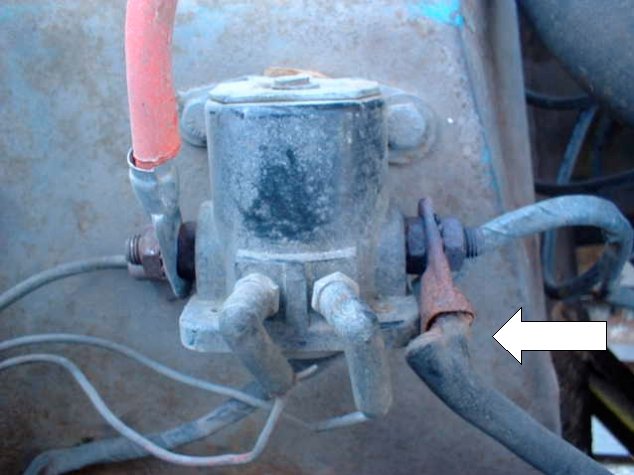
Fig 2 Arrow points to bad cable. Note insulation has overheated and peeled away. Wire is corroded inside cable terminal end.