• Welcome to ClassicBroncos! - You are currently viewing the forums as a GUEST. To take advantage of all the site features, please take a moment to register. It's fast, simple and absolutely free. So please join our community today!
    If you have problems registering or can't log into your account, please contact Admin.

OBD II Engine/Transmission Swap - The Next Generation

OP
OP
Dave

Dave

Contributor
Bronco Guru
Joined
Aug 25, 2006
Messages
2,264
Fuel Tank

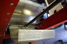
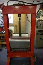
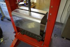
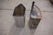
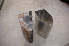
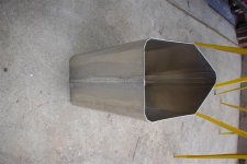
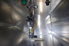
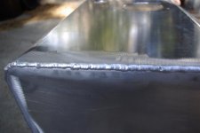
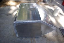
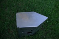
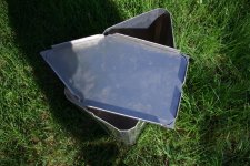
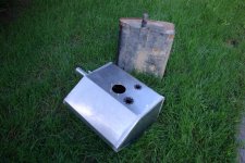
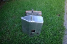
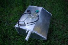
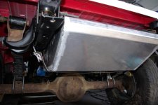
Making some progress on the fuel tank. Got it bent up and did some welding today. First "this one counts" TIG weld came out pretty nice. The tank is the same basic shape as the stock and will mount in the same location. It is 12 1/2" deep to accomodate the Explorer fuel pump assembly which bolts in from the top. The 1" body lift will allow enough room for the fuel line and wires mounting the tank on the stock mounts. It should have a capacity of about 18 gallons. I'm going to put a baffle in it and cut the ends out today.
 

Attachments

  • IMGP0002-1 (Large).JPG
    IMGP0002-1 (Large).JPG
    72.3 KB · Views: 124
  • IMGP0003-1 (Large).JPG
    IMGP0003-1 (Large).JPG
    55.2 KB · Views: 122
  • IMGP0004-1 (Large).JPG
    IMGP0004-1 (Large).JPG
    70 KB · Views: 114
  • IMGP0001 (Large).JPG
    IMGP0001 (Large).JPG
    81.2 KB · Views: 114
  • IMGP0002 (Large).JPG
    IMGP0002 (Large).JPG
    84.1 KB · Views: 102
  • IMGP0003 (Large).JPG
    IMGP0003 (Large).JPG
    98.6 KB · Views: 102

Hal9000

Bronco Guru
Joined
Oct 12, 2008
Messages
1,324
Loc.
Flagstaff, AZ
Damn, I want your shop....

That tank looks good so far. I can't wait to see how your rig turns out when its done! I bet you'll quickly get tired of saying "I made that myself" when people ask where you got your parts.
 

Tito

CB Fire Starter
Joined
Jan 29, 2006
Messages
10,781
Loc.
Bakersfield, CA
Hey Dave, how much for one of those good buddy? No Seriously, how much, I've got an explorer motor to install this spring in my halfcab.
 
OP
OP
Dave

Dave

Contributor
Bronco Guru
Joined
Aug 25, 2006
Messages
2,264
Hey Dave, how much for one of those good buddy? No Seriously, how much, I've got an explorer motor to install this spring in my halfcab.


Lets see how the final product comes out first. Takes about $100 worth of 5052 and $30 in argon and rod. So far.
 

cougarmandan

Sr. Member
Joined
May 13, 2007
Messages
370
Loc.
Bonanza, AR
Wow, Good Stuff, NO, GREAT STUFF!!! 2 days, now and I finally read all through your thread. I was working on wiring up a 99 Cobra motor several years ago and basically stopped moving forward since there weren't any used parts or info out there on the pats at the time. I read up on how the pats talks directly with the PCM if it wasn't passing the right code, the PCM shuts down the motor. If its all in the PCM, I figured a good programmer could just tell it to ignore it or take it out completely. I remember talking to several people at Diablo about getting a custom tune and having the pats removed from the computer. They said it could be done, then they said it couldn't be done, then about 6 months later, they were advertising it in all the magazines that they could so I guess they did figure it out after all. So you can get just about any setup out there and have the pats disabled from the PCM. I guess the theory being if someone wants your vehicle bad enough, they will find a way. I read that PATS decreased Mustang thefts by 75% when they installed it in 1996. (I guess the other 25% used tow trucks.) That to me makes it a worth while investment when you figure how uncomplicated it really is. This thread gets me fired up though. And I agree that this stuff isn't too complicated once you get it figuared out. Take it one wire at a time. 93 Mustang compared to what your doing really isn't very much harder. You just have to look at the wiring diagrams and components individually and it doesn't take long until you have a complete harness setup. Speaking of which, I found the factory Ford wiring diagram on ebay for like $20 for the Mustang and they are simply worth every penny. I haven't ever used alldata, but I like having a book I can set on the workbench and reference it as I trace and make my wires. It shows all the connectors, pin numbers, component locations and so on. It may be the same stuff you are getting on alldata, but its a good source if you don't want to pay the alldata fees, not to mention, it the original source.

I did have a couple of questions about your setup. Are you going to grind the key to fit you existing locks or do you have another plan (like removing the pats chip from the key and epoxying it to your Bronco key. There used to be some clear PATS keys on ebay that you easily see where to cut the plastic to get the chip out. I didn't figure the PATS key locks could be installed in the Bronco. I know Ford's NGS tool (new generation scanner) can do alot of the functions you are doing as well as program new pats keys. I have considered getting one from time to time, but they are very expensive. I was hoping someone would come out with a cheaper scan tool or software that would allow the advanced DIY'er to do it. I honestly haven't looked into it in a while.
I also notice you seam concerned about vss signals. I ran a 97 Mustang about a year without a speedo gear at all and didn't throw a code. I was always amazed it didn't throw a code. I read up on it a little a while back but its been a while. Since it was a manual transmission, I thought it was only necessary for verifying/comparing optimal engine load calculations and estimating things like fuel ratio, idle speed when letting off the gas when coasting and stopping and such. When I read you posts, my thought it that you may need it since its an automatic, but you may not. I have read it many times that the PCM will learn after an hour of driving and it may not matter as long as it has some kind of signal to learn from, weather it be 8 or 16 or 2. Using your method, there is absolutely no question its right, but I was thinking it might be possible for someone with a manual or who has a less intensive build up to get by with out the vss signal. If you think about, you can rev the engine up in park, and the vss is zero, and the computer has no reason to throw a code. Even some of the commercial duty stuff that has PTO's would essentially have a zero VSS signal, yet the engine could be under quite a heavy load. However, after reading your posts, I feel it might more negatively effect the performance than I previously thought. The Mustang was supercharged so it was really hard to tell if it was effected. No speedo, so you don't know how many miles you have traveled so you can't check MPG either. Anyways, thoughts that was popping into my head. I was looking at E4OD trans controllers a while back and there are a few companies out there that make a signal converter. I remember being referred by Baumann when I got a baumannator for my 48 F-1 project. I am going the other way on signal, but I will have to look it up and see who it was because I thought they had both. Point being, someone makes them, I just can't remember who at this moment.
 

744x4

Sr. Member
Joined
May 31, 2006
Messages
611
Loc.
Taylors,SC
This is one of the best write-ups I have ever read.You actually explain it and show some pictures of what you did.I have a 5.0 Mustang setup I just pulled from my driver after it gave me problems and in its place it now has a Howell EFI injected 302 but I havent lost all faith in the Ford EFI just yet as the 5.0 will be used in my Buggy project.

Thanks for the excellent write-up
 
OP
OP
Dave

Dave

Contributor
Bronco Guru
Joined
Aug 25, 2006
Messages
2,264
Fuel tank progress

Got back from vacation in Michigan and have been playing catchup at work. Finally got some time for the project.

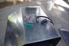
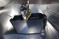
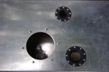
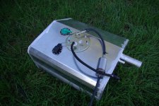
I bent up the end caps and welded one side in. Went from a 80% ballance to 70% and it really made a difference on the 1052 aluminum. Ballance is the time the work piece is negative vs electrode negative. More cleaning but the torch gets hotter. Someday I'll break down and get a water cooled torch. The welds are comming out real nice. The pump is the stock Explorer pump assemble which contains the pump, level sensor, pressure regulator, and screen. The return type system is identical but has no regulator and has a return line. The black box is the fuel collector from the Explorer tank. Pretty cute design with channels that wrap around so fuel can not escape durring acceleration and decceleration, and side to side tilt. The other thingies on the top are the fuel tank pressure sensor (emissions) and the check ball safety vent. I also cut the flanges out of the Explorer tank for the vent and pressure transducer. I installed them with soft aviation rivets and used Locktite form-a-gasket. The studs for the pump assembly are stainless panhead screwed up from the bottom and sealed with high strength (red) Locktite.

Monday Update: It's done! Pressure tested and no leakes in my welds. Big improvement over the welds on the test tank. Cleaned the backside of the weld areas and removed more metal on the plasma cuts along with pracitce on technique. Got perfectly clean puddles with no pin holes. When everything comes together TIG welding realy runs nice beads.

Here are the TIG parameters I used.

Metal: .125" 5052 Aluminum
Filler: ER 5356 3/32"
Pure tungsten 3/32"
.1 sec pre flow (I manually purge it stepping on the peddle)
20 Amp hot start
150 amp max
75 Hz
25% ballance
10 sec post flow
Argon 17 Cu Ft/hr #6 gas lense


Off to work today for 5 days on the road. A bunch of that will be in Anchorage so I hope to do some fishing and maybe some float flying with some friends up there.

Next step will be to lift the tub back off and build a crossmember for the 4R70W and get the rest of the drive train installed. I've got to decide what axles to use out of the collection I've aquired. First choice for the front would be the 44 out of the 72 I parted out except there is some pretty severe pitting on the tubes and nuckles. I've got a nice clean HP that I might pull the tubes on outers and stick them on the 44 housing.
 

Attachments

  • fuel tank 008 (Large).jpg
    fuel tank 008 (Large).jpg
    80 KB · Views: 147
  • fuel tank 007 (Large).jpg
    fuel tank 007 (Large).jpg
    67.7 KB · Views: 203
  • fuel tank 005 (Large).jpg
    fuel tank 005 (Large).jpg
    62.9 KB · Views: 200
  • fuel tank 002 (Large).jpg
    fuel tank 002 (Large).jpg
    57.7 KB · Views: 149
  • fuel tank 001 (Large).jpg
    fuel tank 001 (Large).jpg
    86.2 KB · Views: 164
  • fuel tank 010 (Large).jpg
    fuel tank 010 (Large).jpg
    116.1 KB · Views: 127
  • fuel tank 013 (Large).jpg
    fuel tank 013 (Large).jpg
    157.6 KB · Views: 138
  • fuel tank 015 (Large).jpg
    fuel tank 015 (Large).jpg
    62 KB · Views: 145
  • fuel tank 025 (Large).jpg
    fuel tank 025 (Large).jpg
    128.5 KB · Views: 163
  • fuel tank 024 (Large).jpg
    fuel tank 024 (Large).jpg
    144.4 KB · Views: 118
  • fuel tank 022 (Large).jpg
    fuel tank 022 (Large).jpg
    150.6 KB · Views: 132
  • fuel tank 026 (Large).jpg
    fuel tank 026 (Large).jpg
    122.9 KB · Views: 160
Last edited:
OP
OP
Dave

Dave

Contributor
Bronco Guru
Joined
Aug 25, 2006
Messages
2,264
Mounting The Tank

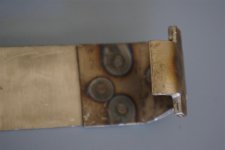
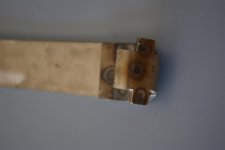
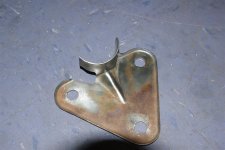
I needed to fabricate a new strap for the bigger tank. I took the ends off the old one and spot welded them on to a piece of stainless that I had laying around. Should look nice with the aluminum tank. The tank fit well. I might have to bend the outlet down slightly on the fuel pump assembly. With a 1 inch body lift it's a little snug. Worst case I can move the rear brackers down 1/2".

Harbor Freight had a Father's day special going so I picked up the 220 volt spot welder for $138. Wouldn't normally buy their welding equipment but they look pretty decent and there are not many parts other than a transformer, switch, an overgrown clamp. It works very nice and is a no brainer to use.
 

Attachments

  • fuel tank 003 (Large).jpg
    fuel tank 003 (Large).jpg
    37.7 KB · Views: 67
  • fuel tank 004 (Large).jpg
    fuel tank 004 (Large).jpg
    30 KB · Views: 63
  • fuel tank 007 (Large).jpg
    fuel tank 007 (Large).jpg
    83.2 KB · Views: 116
Last edited:
OP
OP
Dave

Dave

Contributor
Bronco Guru
Joined
Aug 25, 2006
Messages
2,264
Steering System

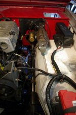
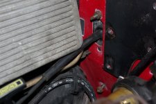
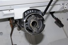
I'm using a converted PS box out of a 79 Bronco and a steering column out of a 78 F100 which had a C4. The F100 column is shorter and has an under dash arm to the shifting shaft for a neutral lockout. I'll modify that to drive the shift cable on the 4R70W.

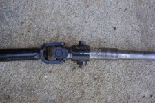
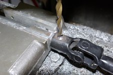
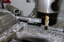
Connecting the EB steering shaft to the BB steering box turned out pretty slick. I used the collapsible shaft from a newer bronco (90ish) along with end of the steering shaft which is hollow and has the same id as the od on the EB steering shaft. That is the stub I cut off the BB laying on the vise. I cut the length on the EB steering shaft and cut some flats on it to fit inside the BB shaft end. (a mill makes it easy but it could be done with some carefull grinding and file work) Drove it on the end of the shaft sith some locktite for good measure and drilled the bolt hole.

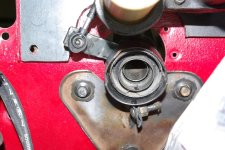
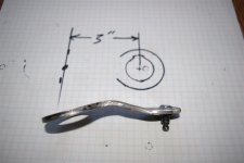
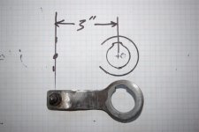
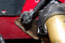
I reshaped the shift arm on the F100 steering column and welded the ball connector from the Explorer shift cable on it. Took a little fitting and math to get correct throw so the shift detents ligned up with the column indicator. Had to cut a notch out of the colum support for the shift arm but everything fits up nicely with the hydroboost moved over. 3 inch radius for the shift arm worked out perfect. I matched the length of Explorer arm and hoped that Ford didn't reinvent the wheel as far as the shift detents and indicator spacing went. It appears to be very compatible with the C4.

edit: The angle on the drawing should be 60 degrees not 30. I'll correct the drawing later.
 

Attachments

  • Steering column 004 (Large).jpg
    Steering column 004 (Large).jpg
    164.5 KB · Views: 349
  • Steering column 003 (Large).jpg
    Steering column 003 (Large).jpg
    113.8 KB · Views: 343
  • Steering column 002 (Large).jpg
    Steering column 002 (Large).jpg
    118.8 KB · Views: 361
  • hydroboost 014 (Large).jpg
    hydroboost 014 (Large).jpg
    64.8 KB · Views: 341
  • Steering column 007 (Large).jpg
    Steering column 007 (Large).jpg
    119.1 KB · Views: 361
  • Steering column 010 (Large).jpg
    Steering column 010 (Large).jpg
    62.2 KB · Views: 386
  • Steering column 005 (Large).jpg
    Steering column 005 (Large).jpg
    84 KB · Views: 297
  • Steering column 006 (Large).jpg
    Steering column 006 (Large).jpg
    88.8 KB · Views: 280
  • hydroboost 030 (Large) (2).jpg
    hydroboost 030 (Large) (2).jpg
    117.5 KB · Views: 341
  • IMGP0014 (Large).JPG
    IMGP0014 (Large).JPG
    52.6 KB · Views: 287
  • IMGP0013 (Large).JPG
    IMGP0013 (Large).JPG
    65.9 KB · Views: 304
  • hydroboost 035 (Large).jpg
    hydroboost 035 (Large).jpg
    94.2 KB · Views: 489
Last edited:
OP
OP
Dave

Dave

Contributor
Bronco Guru
Joined
Aug 25, 2006
Messages
2,264
Astroboost

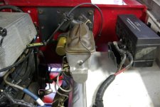
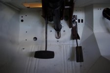
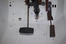
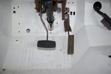
Just completed the mounting bracket for the hydroboost. I'm moving the brake pedal to the clutch position and mounting the unit outboard. Looks like it's going to work out very well. I should even have room to for the cable shifter.

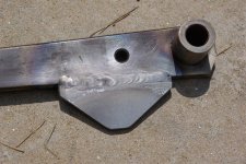
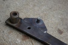
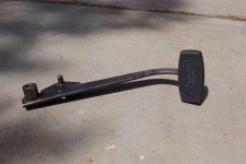
I heated the brake pedal arm and straightened the bends. Welded on a tab and to moved the pushrod pivot down about 1/2" to match the throw of the Hydroboost. I also moved it forward to avoid having to extend the pushrod. Mostly so a stock unit will fit if this one ever fails. The hydroboost could have been mounted about 1/2" inboard and 1/2 lower to be perfect but it the angles are close enough for smooth operation. I'll look for a big pedal at the junk yard tomorrow. I'll probably mount it with a little offset to the right. So far the total astroboost project cost is under $30. Hydraulic lines will add a few more bucks.

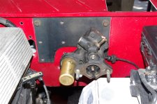
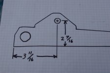
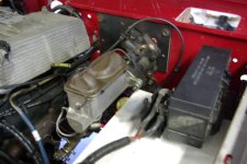
Added the dimensions and mastercylinder pictures. The master cylinder and H block are out of the Lincoln that I pulled the first hydroboost out of. I had 4 wheel disks. The hydroboost is out of a 93 astrovan AWD. Deleting the clutch and moving the brake pedal to the clutch position really frees up a bunch of space.

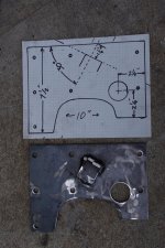
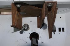
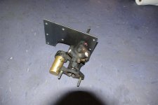
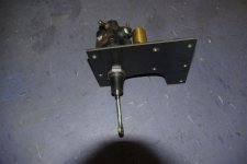
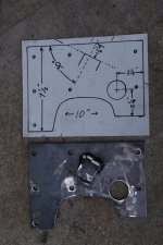
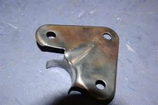
The last picture is the adaptor plate with dimensions for the hole and Explorer shift cable bracket. I welded it on and hope that I don't regret not mounting it with bolts and slotted holes for adjustment.
The adaptor plate is 10" by 7 1/2". I just realized that the hole is located with a floating dimension. Make it 4" from the top of the plate.

I orderded a brake pedal rubber with Bronco script from WH. Turns out that it fits perfectly on a Explorer brake pedal so I cut one off at the yunk yard and welded it on. Last picture.
 

Attachments

  • Hydroboost 010 (Large).jpg
    Hydroboost 010 (Large).jpg
    55.7 KB · Views: 162
  • Hydroboost 007 (Large).jpg
    Hydroboost 007 (Large).jpg
    74.8 KB · Views: 128
  • Hydroboost 006 (Large).jpg
    Hydroboost 006 (Large).jpg
    69 KB · Views: 140
  • Hydroboost 009 (Large).jpg
    Hydroboost 009 (Large).jpg
    116.5 KB · Views: 175
  • hydroboost 018 (Large).jpg
    hydroboost 018 (Large).jpg
    149 KB · Views: 120
  • hydroboost 020 (Large).jpg
    hydroboost 020 (Large).jpg
    87.3 KB · Views: 124
  • hydroboost 024 (Large).jpg
    hydroboost 024 (Large).jpg
    56.6 KB · Views: 110
  • hydroboost 026 (Large).jpg
    hydroboost 026 (Large).jpg
    83.9 KB · Views: 186
  • hydroboost 029 (Large).jpg
    hydroboost 029 (Large).jpg
    82.6 KB · Views: 205
  • hydroboost 030 (Large) (2).jpg
    hydroboost 030 (Large) (2).jpg
    117.5 KB · Views: 158
  • hydroboost 045 (Large).jpg
    hydroboost 045 (Large).jpg
    100.7 KB · Views: 124
  • hydroboost 003 (Large).jpg
    hydroboost 003 (Large).jpg
    48.5 KB · Views: 199
Last edited:
OP
OP
Dave

Dave

Contributor
Bronco Guru
Joined
Aug 25, 2006
Messages
2,264
The phinal phase

I've got all of the retrofit work done so its now time to put it all together. The tub is just sitting on the frame so I'll pull it back off to clean things up and paint the interior and engine compartment. I also have to fabricate a cross member and figure out what axles to put under it. I'll finish all of the drivetrain and suspension work with the tub off. I've also got a lot of little parts to clean and powdercoat. Work has been keeping me busy so my plans of having it on the road this summer are not looking good. Maybe some fall rides and some road trips next summer.
Happy Inedpendence Day everyone. Please remember the rights and freedoms that our country has fought to achieve and preserve.
 
Last edited:

Hal9000

Bronco Guru
Joined
Oct 12, 2008
Messages
1,324
Loc.
Flagstaff, AZ
Welded on a tab and to moved the pushrod pivot down about 1/2" to match the throw of the Hydroboost.

Nice work Dave. I'm curious how you figured out that the throw for the HB unit was longer than what was provided by the stock arm? I would probably have missed that completely.
 

flousberg

Sr. Member
Joined
Apr 28, 2002
Messages
745
I'm using a converted PS box out of a 79 Bronco and a steering column out of a 78 F100 which had a C4. The F100 column is shorter and has an under dash arm to the shifting shaft for a neutral lockout. I'll modify that to drive the shift cable on the 4R70W.

Connecting the EB steering shaft to the BB steering box turned out pretty slick. I used the collapsible shaft from a newer bronco (90ish) along with end of the steering shaft which is hollow and has the same id as the od on the EB steering shaft. That is the stub I cut off the BB laying on the vise. I cut the length on the EB steering shaft and cut some flats on it to fit inside the BB shaft end. (a mill makes it easy but it could be done with some carefull grinding and file work) Drove it on the end of the shaft sith some locktite for good measure and drilled the bolt hole.

I reshaped the shift arm on the F100 steering column and welded the ball connector from the Explorer shift cable on it. Took a little fitting and math to get correct throw so the shift detents ligned up with the column indicator. Had to cut a notch out of the colum support for the shift arm but everything fits up nicely with the hydroboost moved over.


Looks like you decided to use the stock explorer cable. Did you get everything to work out on the shift points? I found the angle was as important as the distance from the center to the pivot point on the arm.
 
OP
OP
Dave

Dave

Contributor
Bronco Guru
Joined
Aug 25, 2006
Messages
2,264
Throttle Cable

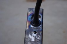
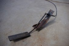
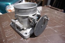
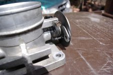
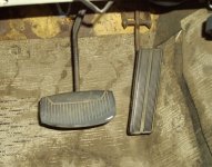
It turned out to be a real easy mod to use the Explorer throttle cable with the Bronco accelerator pedal assembly.

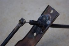
I welded up the two holes that hold the shaft boot on and drilled up the hole that the shaft goes through to fit the Explorer cable housing. I ground the end of the ball that the shaft pops on and drove it out. Heated up the pedal arm and twisted it 90 degrees and drilled up the hole for the end of the cable. I ran a couple beads of weld to build the sides of the indentation so I could hog out a flat surface for the seal on the cable housing.

I drilled and tapped a 10-32 hole in the end of the throttle shaft so I could mount the disk with the ball for the end of the cable. I can adjust it and lock it in place with a screw through the origional hole in the arm. I decided to rotate the throttle body with linkage on the bottom and the cable looping around the front of the engine. It makes a very nice loop and works smoothly. The peddal has a great feel as far a the throw and spring action. I tack welded a tab on the valve cover next to the filler neck for the cable. I'll pull the valve cover and do the final weld and powder coat it.
 

Attachments

  • hydroboost 049 (Large).jpg
    hydroboost 049 (Large).jpg
    42.8 KB · Views: 142
  • hydroboost 048 (Large).jpg
    hydroboost 048 (Large).jpg
    48.7 KB · Views: 152
  • hydroboost 047 (Large).jpg
    hydroboost 047 (Large).jpg
    94.6 KB · Views: 149
  • hydroboost 002 (Large).jpg
    hydroboost 002 (Large).jpg
    48.6 KB · Views: 140
  • hydroboost 005 (Large).jpg
    hydroboost 005 (Large).jpg
    85 KB · Views: 140
  • Steering column 004 (Large).jpg
    Steering column 004 (Large).jpg
    90.2 KB · Views: 143
  • Steering column 005 (Large).jpg
    Steering column 005 (Large).jpg
    84.3 KB · Views: 120
  • Steering column 002 (Large).jpg
    Steering column 002 (Large).jpg
    127.3 KB · Views: 147
  • Steering column 003 (Large).jpg
    Steering column 003 (Large).jpg
    146.9 KB · Views: 150
Last edited:

Viperwolf1

Contributor
electron whisperer
Joined
Aug 23, 2007
Messages
24,342
Looks like it should come over quite a bit. This is my '74 with the wide pedal.
 

Attachments

  • Bronco 342.jpg
    Bronco 342.jpg
    249 KB · Views: 43
OP
OP
Dave

Dave

Contributor
Bronco Guru
Joined
Aug 25, 2006
Messages
2,264
Looks like it should come over quite a bit. This is my '74 with the wide pedal.


Thanks for the pic. I bent it over about 2 inches to the right.
 

Attachments

  • hydroboost 007 (Large).jpg
    hydroboost 007 (Large).jpg
    52.6 KB · Views: 111
Last edited:

Bronco73

Bronco Guru
Joined
May 29, 2003
Messages
2,989
Loc.
Cape Coral, FL
This has my interest as I am pulling a complete 98 explorer motor and trans Monday morning, while I'm on vacation. I also snagged the wiring and computrer from a 2000 explorer.
 
OP
OP
Dave

Dave

Contributor
Bronco Guru
Joined
Aug 25, 2006
Messages
2,264
This has my interest as I am pulling a complete 98 explorer motor and trans Monday morning, while I'm on vacation. I also snagged the wiring and computrer from a 2000 explorer.


One caution: The 98 has a return type fuel rail and the 2000 will be a returnless. I believe there will be some computer differences.
 
Top