


Tech article by Phil Dawson (phldwsnoc1)
After a career of making suspension repairs and improvements to a wide variety of vehicles, it was time to see if I could do the same for my Bronco. Designed with a single adjustment point for total toe, some creativity is in order when you approach alignment issues on these products. It’s also important to bear in mind that unless you are doing a pure restoration with original wheel and tires, factory specs may not be at all appropriate to achieve your desired results. Which, by the way, will be the same for nearly all of us:
Maximize steering control and tire life.
Those of us who spend most of our time on pavement just want the bloody truck to behave while we’re driving, and we’d like to preserve those tires on which we spent a small fortune. That’s the perspective of this article. Others may have differing intentions with their trucks. I will read their experiences with interest.
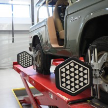
There are a host of clever and effective methods for measuring some alignment angles, but I have opted for a thoroughly modern approach. I will make the hour drive to my employer’s training facility and take measurements with a Hunter DSP 600 aligner. You may need to make friends with your local service provider to get similar data. Ask to speak directly with the human that will be measuring your angles. Make sure they understand precisely what you are looking for. If you are not sure they are interested, find another service provider. Depending on the condition of your rig at the start and the results you are looking for, this exercise may or may not be an option. Certain key alignment data cannot be measured directly, as I will explain later.
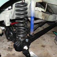
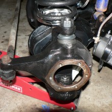
Certain conditions must be established prior to taking any measurements, such as the condition of ball joints, tie rod ends, wheel bearings, tire pressures, suspension height, etc. If incorrect measurements or clearances exist it is a waste of time to measure alignment angles, as your measurements will not reflect real operating conditions. For me, this exercise was taking place near the end of a much larger project, in which I was doing a wheel to wheel refresh of a D44, including a disc brake conversion. If you have interest in other parts of that process, please send your requests to the webmaster or the address at the end of this article.
Now for the essentials of front wheel alignment. There is no shortage of illustrations available on the web for these, so I haven’t included my own. We have three primary alignment angles:
Toe
As the only steering angle with a factory adjustment on the Bronco, this must be pretty important. There are low-tech methods for measuring toe, which can be done with reasonable levels of accuracy. These methods are widely available on the interweb.
Does toe cause pull? No, at least not by itself. Drastically incorrect toe can cause darting and very unstable handling, but incorrect toe alone does not cause consistent, steady pulling to one side. Ever. This is because when you are driving, each front wheel will automatically assume half of the total toe.
Does incorrect toe cause tire wear? Yes. Incorrect toe is a major contributor to tire wear.
Should my toe be set to factory specs? If you are doing a pure restoration with original equivalent tires, yes. For most of us with modern tires, no. Toe should also be the very last adjustment you make with regard to wheel alignment, as pretty much all other adjustments will affect toe.
Camber
This is the lean of the wheel as compared to vertical. Positive camber means the wheel is leaning outward at the top, negative means it is leaning inward. Zero camber means the wheel is dead vertical. No factory camber adjustments are provided on the D44 axle, but there are good options for correction. Again, there are low-tech measurement options that will get you in the ballpark.
Does camber cause pull? Yes, it causes pull to the side with the MOST positive camber. All else being equal, the severity of the pull will be in proportion to the cross camber, or difference in camber from side to side.
Does incorrect camber cause tire wear? Yes. Incorrect camber is a major contributor to tire wear.
Should my camber be set to factory specs? Spec on my rig is 1.5 degrees positive, plus or minus 0.5 degrees. That is a LOT of camber. With wider wheels and tires, I will aim for something much lower.
Caster
This is the steering axis created by the ball joints as viewed from the side, relative to vertical. Positive caster means the top ball joint is angled to the rear of the axle in relation to the lower ball joint. Negative caster, in almost every case, means something is way wrong and is usually only seen after a crash. Again, no adjustments are provided, but we have options for correction. Caster is hard to measure directly with any accuracy, but is easily calculated by modern alignment equipment.
Does incorrect caster cause pull? Yes, it causes pull to the side with the LEAST positive caster. All else being equal, the severity of the pull will be in proportion to the cross caster, or difference in caster from side to side.
Does incorrect caster cause tire wear? The short answer is no, not directly.
Increased caster improves on-center stability, but also requires more steering effort at low speeds. So while more may be better to a point, power assist changes the picture in terms of what is reasonable.
We then have a couple of diagnostic angles. These are used to determine if something is bent or damaged:
Steering Axis Inclination (SAI)
This calculation is similar to caster, and determines the angle of the axis created by the ball joints as viewed from the front relative to vertical. It will tell us if the ball joints are placed properly from this perspective, or if the axle has been stressed beyond design limitations. If it’s bent, in other words. If this measurement is wrong, we may be able to correct it depending on the severity of the condition.
Included Angle (IA)
IA is simply a combination of camber and SAI. This one is super helpful in finding a bent knuckle or spindle. Imagine that the ball joints are in the right spot, but camber is not even close. That means something BETWEEN the joints is out of position. IA will help with this diagnosis.
The real magic is in looking at the whole alignment picture, and finding the easiest, high leverage corrections to support our objective as stated above. We have to consider what is known as “stacked tolerances,” or the interaction of all of these variable components. Most cars will behave well under a wide variety of conditions, but even if all measurements are within the specified range the combined results may be rubbish. We should also consider practicality in making adjustments. Rather than buy all the shims and sleeves to adjust every measurement to a precise, predetermined point, it usually works out to identify which side of the axle is already closest to ideal, and simply adjust the other side to accommodate. So here we go with my personal Bronco experience.
Given that the future wheels and tires on this rig will NOT be original, the factory specifications are for amusement only. I will likely be squeezing some larger feet under the truck, and maintaining my Armstrong steering for some period of time. So camber will be much more vertical than specification. Caster will be on the high side of spec for handling, but near spec so I can still turn the wheels without power assist. When final wheel selection is done, I will attempt to keep the negative offset, but radials will probably prefer a toe-in condition near zero. Even with a lot of prior experience, I have to accept that my first attempts at finding the “sweet spot” may not be my last.
The Bronco was behaving well on the trip to the alignment rack, so I was feeling like there might be no adjustments needed. No such luck.
The measurements taken on the alignment equipment were as such:
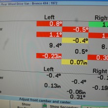
Not at all what I expected. Let’s take it apart:
Cross camber is high, but left side camber is probably good! If I can set the right side to match, it is a reasonable starting point. Should I use a camber shim at the spindle or eccentric sleeve at the ball joint? Hold that question; SAI will give the answer.
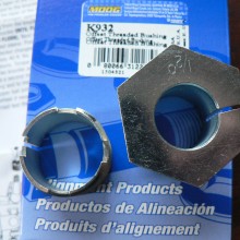
Cross caster is marginally high, but caster overall is way low. I remember that the front of this truck was lifted years ago, but the unseen effects of the longer springs were to rotate the axle forward and steal over half of the specified caster. The installed stock C bushings are 2 degrees. I need to add about 2 more to get the caster I’m looking for. 2(installed)+2(desired increase)=4. I need some 4 degree C bushings. To get the left side caster to match the right, I can install a 0.5 degree eccentric sleeve at the upper ball joint as well. Increased caster should improve on-center handling performance and stability. It will also improve what is known as “camber roll,” or the increase in camber on the inside wheel during a turn. This enhances steering stability and responsiveness when turning, if you dare imagine such a thing on a Bronco.
SAI is high on the left, meaning the left side of the axle probably took a hit at some point. As a side note, impacts on the front wheels almost always bend things UP and IN, and nearly never the reverse. This is a classic case in that regard. The difference in SAI results in a nearly identical difference in camber. If I use an eccentric sleeve at the upper ball joint to adjust the right side SAI to match the left, it will have the consequence of reducing the right side camber to match the left. Two birds, one stone. A camber shim, on the other hand, will change camber only. This would leave the mismatched SAI and resulting oddities in handling. So SAI gives me the answers I need in terms of which type of camber correction will be most effective.
So with over half a degree in cross camber, why was it not pulling to the right? You will notice that the MORE positive right side camber was nearly offset by the LESS positive left side caster. This is a friendly condition, resulting in a car that goes relatively straight in spite of a host of alignment problems. I will need two 0.5 degree bushings, one to decrease right side camber, and one to increase left side caster.
IA is nearly identical side to side. With brand new disc brake spindles, it should be.
Toe will be adjusted after all else is done, so I’m not concerned with it now. It should be the final adjustment, as almost any other change you make will mess with toe.
I found everything on my shopping list at EnergySuspensionParts.com. By the time I get everything apart and ready for final assembly, the parts should be sitting on my porch.
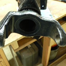
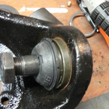
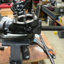
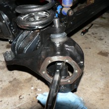
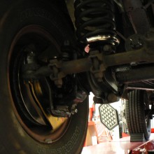
My parts order arrived on Christmas Eve, but the ball joint eccentrics were not in the box. Oh well, at least I can get started with the C bushings. This requires an almost complete removal of the front axle, but with knuckles already removed for other reasons I will have good access to all the related hardware. Be sure to check the print on the inside of the bushings to insure they get installed with the correct orientation. Pull the axle into place with a few threads at a time on the cap bolts. I did this with the radius arms installed and hanging by the shocks to avoid bushing windup during installation. Failure to have the arms at equal angles side to side when tightening the caps can result in a confounding suspension lean condition after assembly. Or so I have read.


Read the instructions that came with your eccentric bushings carefully. They do a pretty good job at steering you away from trouble, no pun intended, and they help you index the bushing to one of eight “clock” positions that will determine the resulting alignment change. I’m looking for all camber reduction on the right side and almost all caster increase on the left, so my installation is pretty straight forward.
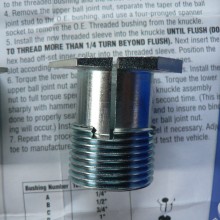
One thing I noticed on assembly was that the torque required to turn the knuckles was much higher with the eccentric bushings than with the original preload sleeve. You will need to sacrifice precision on the preload to use this correction method. This would translate into a hint of memory steer on my initial test drive, although I suspect this condition will self-correct with some time and mileage. I was pleasantly surprised with the handling results other than that. Now I just needed to take the trip back to the alignment rack to confirm my new angles. And these are the results:
Steering should feel more precise on center, and steering effort should actually be a bit higher, due to both added caster and increased ball joint preload.
In fact, I did not get the expected caster change with the 4 degree C bushings, but it is improved. Camber is just a bit higher than target, but as close as you could ask for side-to-side. SAI and IA are pretty well improved, and not likely to create any drama. Along with the other changes made during this project, I feel pretty good about the improvements. My first real road trip will give me some time to get to know this new rig.
Please set the author straight. Your feedback on the effectiveness of this article is requested. Please send your suggestions for improvement or requests for other topics to the webmaster or to phldwsn@zoominternet.net.
Tech article by Phil Dawson (phldwsnoc1)


After a career of making suspension repairs and improvements to a wide variety of vehicles, it was time to see if I could do the same for my Bronco. Designed with a single adjustment point for total toe, some creativity is in order when you approach alignment issues on these products. It’s also important to bear in mind that unless you are doing a pure restoration with original wheel and tires, factory specs may not be at all appropriate to achieve your desired results. Which, by the way, will be the same for nearly all of us:
Maximize steering control and tire life.
Those of us who spend most of our time on pavement just want the bloody truck to behave while we’re driving, and we’d like to preserve those tires on which we spent a small fortune. That’s the perspective of this article. Others may have differing intentions with their trucks. I will read their experiences with interest.
There are a host of clever and effective methods for measuring some alignment angles, but I have opted for a thoroughly modern approach. I will make the hour drive to my employer’s training facility and take measurements with a Hunter DSP 600 aligner. You may need to make friends with your local service provider to get similar data. Ask to speak directly with the human that will be measuring your angles. Make sure they understand precisely what you are looking for. If you are not sure they are interested, find another service provider. Depending on the condition of your rig at the start and the results you are looking for, this exercise may or may not be an option. Certain key alignment data cannot be measured directly, as I will explain later.
Certain conditions must be established prior to taking any measurements, such as the condition of ball joints, tie rod ends, wheel bearings, tire pressures, suspension height, etc. If incorrect measurements or clearances exist it is a waste of time to measure alignment angles, as your measurements will not reflect real operating conditions. For me, this exercise was taking place near the end of a much larger project, in which I was doing a wheel to wheel refresh of a D44, including a disc brake conversion. If you have interest in other parts of that process, please send your requests to the webmaster or the address at the end of this article.
Now for the essentials of front wheel alignment. There is no shortage of illustrations available on the web for these, so I haven’t included my own. We have three primary alignment angles:
Toe
As the only steering angle with a factory adjustment on the Bronco, this must be pretty important. There are low-tech methods for measuring toe, which can be done with reasonable levels of accuracy. These methods are widely available on the interweb.
Does toe cause pull? No, at least not by itself. Drastically incorrect toe can cause darting and very unstable handling, but incorrect toe alone does not cause consistent, steady pulling to one side. Ever. This is because when you are driving, each front wheel will automatically assume half of the total toe.
Does incorrect toe cause tire wear? Yes. Incorrect toe is a major contributor to tire wear.
Should my toe be set to factory specs? If you are doing a pure restoration with original equivalent tires, yes. For most of us with modern tires, no. Toe should also be the very last adjustment you make with regard to wheel alignment, as pretty much all other adjustments will affect toe.
Camber
This is the lean of the wheel as compared to vertical. Positive camber means the wheel is leaning outward at the top, negative means it is leaning inward. Zero camber means the wheel is dead vertical. No factory camber adjustments are provided on the D44 axle, but there are good options for correction. Again, there are low-tech measurement options that will get you in the ballpark.
Does camber cause pull? Yes, it causes pull to the side with the MOST positive camber. All else being equal, the severity of the pull will be in proportion to the cross camber, or difference in camber from side to side.
Does incorrect camber cause tire wear? Yes. Incorrect camber is a major contributor to tire wear.
Should my camber be set to factory specs? Spec on my rig is 1.5 degrees positive, plus or minus 0.5 degrees. That is a LOT of camber. With wider wheels and tires, I will aim for something much lower.
Caster
This is the steering axis created by the ball joints as viewed from the side, relative to vertical. Positive caster means the top ball joint is angled to the rear of the axle in relation to the lower ball joint. Negative caster, in almost every case, means something is way wrong and is usually only seen after a crash. Again, no adjustments are provided, but we have options for correction. Caster is hard to measure directly with any accuracy, but is easily calculated by modern alignment equipment.
Does incorrect caster cause pull? Yes, it causes pull to the side with the LEAST positive caster. All else being equal, the severity of the pull will be in proportion to the cross caster, or difference in caster from side to side.
Does incorrect caster cause tire wear? The short answer is no, not directly.
Increased caster improves on-center stability, but also requires more steering effort at low speeds. So while more may be better to a point, power assist changes the picture in terms of what is reasonable.
We then have a couple of diagnostic angles. These are used to determine if something is bent or damaged:
Steering Axis Inclination (SAI)
This calculation is similar to caster, and determines the angle of the axis created by the ball joints as viewed from the front relative to vertical. It will tell us if the ball joints are placed properly from this perspective, or if the axle has been stressed beyond design limitations. If it’s bent, in other words. If this measurement is wrong, we may be able to correct it depending on the severity of the condition.
Included Angle (IA)
IA is simply a combination of camber and SAI. This one is super helpful in finding a bent knuckle or spindle. Imagine that the ball joints are in the right spot, but camber is not even close. That means something BETWEEN the joints is out of position. IA will help with this diagnosis.
The real magic is in looking at the whole alignment picture, and finding the easiest, high leverage corrections to support our objective as stated above. We have to consider what is known as “stacked tolerances,” or the interaction of all of these variable components. Most cars will behave well under a wide variety of conditions, but even if all measurements are within the specified range the combined results may be rubbish. We should also consider practicality in making adjustments. Rather than buy all the shims and sleeves to adjust every measurement to a precise, predetermined point, it usually works out to identify which side of the axle is already closest to ideal, and simply adjust the other side to accommodate. So here we go with my personal Bronco experience.
Given that the future wheels and tires on this rig will NOT be original, the factory specifications are for amusement only. I will likely be squeezing some larger feet under the truck, and maintaining my Armstrong steering for some period of time. So camber will be much more vertical than specification. Caster will be on the high side of spec for handling, but near spec so I can still turn the wheels without power assist. When final wheel selection is done, I will attempt to keep the negative offset, but radials will probably prefer a toe-in condition near zero. Even with a lot of prior experience, I have to accept that my first attempts at finding the “sweet spot” may not be my last.
The Bronco was behaving well on the trip to the alignment rack, so I was feeling like there might be no adjustments needed. No such luck.
The measurements taken on the alignment equipment were as such:
| Left | Right | Cross | |
| Camber | 0.7 | 1.3 | 0.6 |
| Caster | 1.1 | 1.5 | 0.4 |
| SAI | 9.4 | 8.9 | 0.5 |
| IA (Camber + SAI) | 10.1 | 10.2 | 0.1 |


Not at all what I expected. Let’s take it apart:
Cross camber is high, but left side camber is probably good! If I can set the right side to match, it is a reasonable starting point. Should I use a camber shim at the spindle or eccentric sleeve at the ball joint? Hold that question; SAI will give the answer.
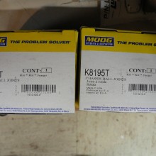
Cross caster is marginally high, but caster overall is way low. I remember that the front of this truck was lifted years ago, but the unseen effects of the longer springs were to rotate the axle forward and steal over half of the specified caster. The installed stock C bushings are 2 degrees. I need to add about 2 more to get the caster I’m looking for. 2(installed)+2(desired increase)=4. I need some 4 degree C bushings. To get the left side caster to match the right, I can install a 0.5 degree eccentric sleeve at the upper ball joint as well. Increased caster should improve on-center handling performance and stability. It will also improve what is known as “camber roll,” or the increase in camber on the inside wheel during a turn. This enhances steering stability and responsiveness when turning, if you dare imagine such a thing on a Bronco.
SAI is high on the left, meaning the left side of the axle probably took a hit at some point. As a side note, impacts on the front wheels almost always bend things UP and IN, and nearly never the reverse. This is a classic case in that regard. The difference in SAI results in a nearly identical difference in camber. If I use an eccentric sleeve at the upper ball joint to adjust the right side SAI to match the left, it will have the consequence of reducing the right side camber to match the left. Two birds, one stone. A camber shim, on the other hand, will change camber only. This would leave the mismatched SAI and resulting oddities in handling. So SAI gives me the answers I need in terms of which type of camber correction will be most effective.
So with over half a degree in cross camber, why was it not pulling to the right? You will notice that the MORE positive right side camber was nearly offset by the LESS positive left side caster. This is a friendly condition, resulting in a car that goes relatively straight in spite of a host of alignment problems. I will need two 0.5 degree bushings, one to decrease right side camber, and one to increase left side caster.
IA is nearly identical side to side. With brand new disc brake spindles, it should be.
Toe will be adjusted after all else is done, so I’m not concerned with it now. It should be the final adjustment, as almost any other change you make will mess with toe.
I found everything on my shopping list at EnergySuspensionParts.com. By the time I get everything apart and ready for final assembly, the parts should be sitting on my porch.
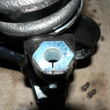
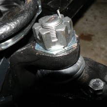
My parts order arrived on Christmas Eve, but the ball joint eccentrics were not in the box. Oh well, at least I can get started with the C bushings. This requires an almost complete removal of the front axle, but with knuckles already removed for other reasons I will have good access to all the related hardware. Be sure to check the print on the inside of the bushings to insure they get installed with the correct orientation. Pull the axle into place with a few threads at a time on the cap bolts. I did this with the radius arms installed and hanging by the shocks to avoid bushing windup during installation. Failure to have the arms at equal angles side to side when tightening the caps can result in a confounding suspension lean condition after assembly. Or so I have read.


Read the instructions that came with your eccentric bushings carefully. They do a pretty good job at steering you away from trouble, no pun intended, and they help you index the bushing to one of eight “clock” positions that will determine the resulting alignment change. I’m looking for all camber reduction on the right side and almost all caster increase on the left, so my installation is pretty straight forward.


One thing I noticed on assembly was that the torque required to turn the knuckles was much higher with the eccentric bushings than with the original preload sleeve. You will need to sacrifice precision on the preload to use this correction method. This would translate into a hint of memory steer on my initial test drive, although I suspect this condition will self-correct with some time and mileage. I was pleasantly surprised with the handling results other than that. Now I just needed to take the trip back to the alignment rack to confirm my new angles. And these are the results:
| Target | Actual Left | Actual Right | Cross | |
| Camber | 0.75 | 0.9 | 0.8 | 0.1 |
| Caster | 3.5 | 2.8 | 2.6 | 0.2 |
| SAI | 9.5 | 9.2 | 9.5 | 0.3 |
| IA (Camber + SAI) | 10 | 10.1 | 10.3 | 0.2 |
In fact, I did not get the expected caster change with the 4 degree C bushings, but it is improved. Camber is just a bit higher than target, but as close as you could ask for side-to-side. SAI and IA are pretty well improved, and not likely to create any drama. Along with the other changes made during this project, I feel pretty good about the improvements. My first real road trip will give me some time to get to know this new rig.
Please set the author straight. Your feedback on the effectiveness of this article is requested. Please send your suggestions for improvement or requests for other topics to the webmaster or to phldwsn@zoominternet.net.
Tech article by Phil Dawson (phldwsnoc1)


