Laxdad
New Member
Guys, first I'll start with what I have, then what's going on, then what and how things are wired. I'll also add I consider myself an above average garage mechanic and have above average skill on diagnosing and problem solving.
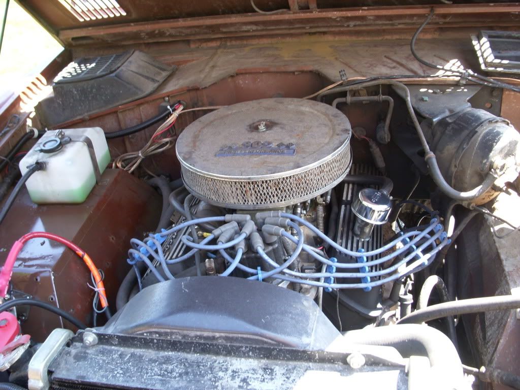
I bought my 77 bronco from a Buddy who did the 3G upgrade /old regulator removal. He also installed a new coil and distributor.
First I have a 130a 3G alternator and I'm only getting about 6-7 volts off the back of it at idle. It doesn't seem to be charging my battery as when the Truck is running the most volts i'm getting at the battery is maybe 11 I've replaced it three times so now I'm pretty sure it's not a bad alternator.
Second, sometimes my bronco won't turn off. I've replaced relay 4 times and now went to solid top post style, ignition switch and starter. It will run fine for a week or a day and then Wham it just won't stop. Today it happened to my son and it killed the battery really quick. When I pulled the I post wire off it seemed to "reset" itself and is now working fine again.
It's almost a viscous circle in the fact that this then kills the battery when I come out to start the bronco, which could be part of my charging problems.
Now the wiring. I have never seen the old regulator as the 3G is internally regulated.
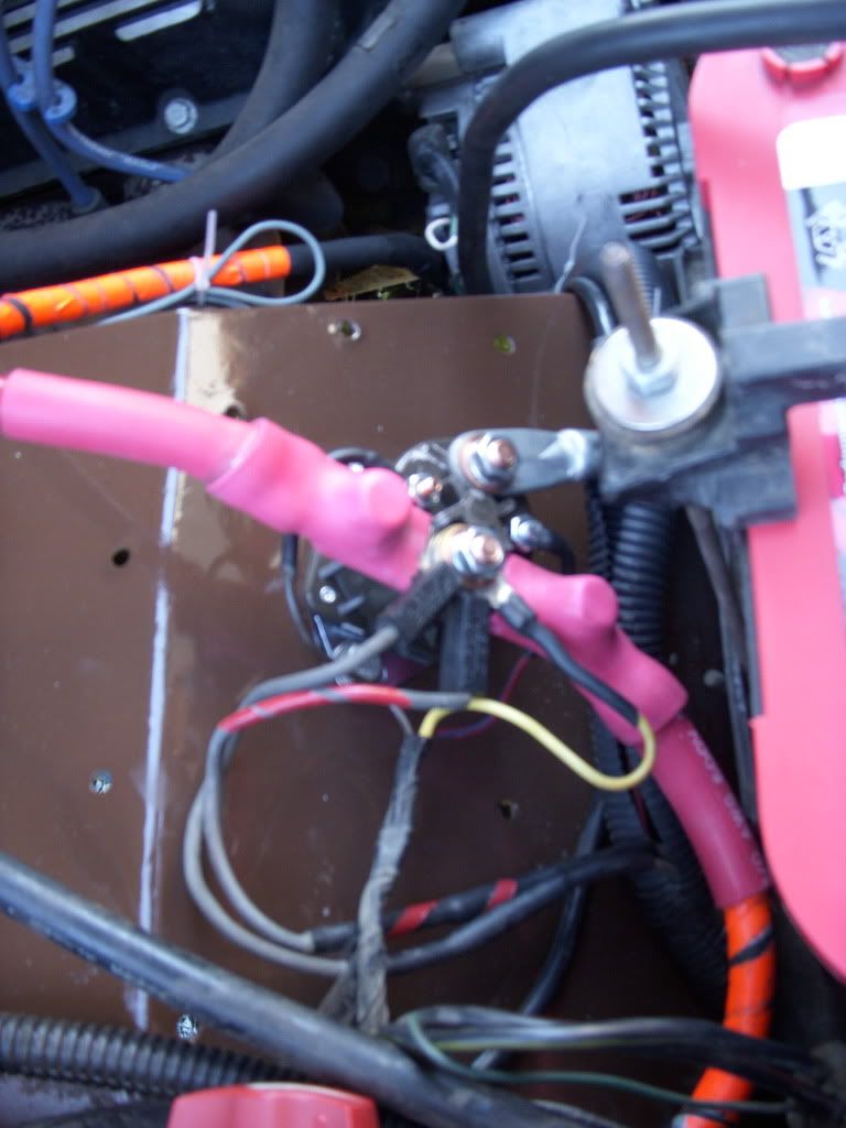
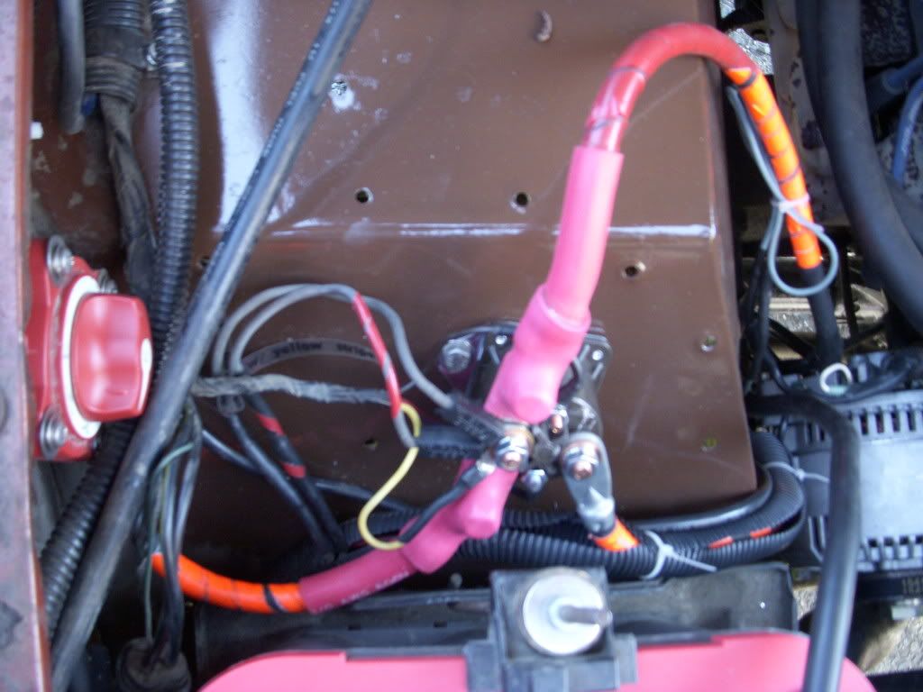
I'll start with starter relay (top post new style napa #STH404)
B Terminal, 0 ga wire to battery, yellow wire from harness, black w/ yellow stripe (fusible link) from harness & black w/ red stripe (fusible link) from harness (both the black wires are about 10-12 ga and go to the same plug with a yellow wire that is going down to the "I" terminal on the alternator.
M Terminal, 0ga wire going to starter.
I Terminal, brown wire from harness ( wiring diagram says this ties into a Red w/ green stripe wire hat goes to coil, but.... On the drivers side coming out of the cab is a Red w/ green stripe wire just cut off. This wire is on the same line as the brown wire as verified by a onto unity check - see below under coil).
S Terminal, Red w/ blue stripe from harness (this goes to back of ignition switch)
All these "harness" wires o through the firewall on the passenger side into the cab.
Alternator, pretty self explanatory.
B+ Terminal, 0ga wire goes to starter relay B
A Terminal, yellow/white wire goes to Alt B+
S Terminal, white/black wire goes to spade on Alt
I Terminal, this wire goes to a yellow wire that is in the same under/connector as the two thicker black wires on the relay B terminal.
Battery
0ga wire from + to starter relay B Terminal
0ga wire from - to frame, I also have a 0ga wire going from frame to block on both sides of engine.
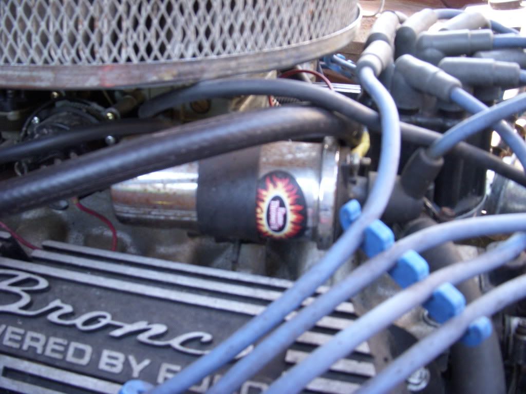
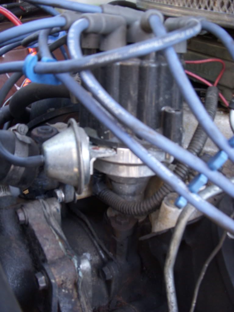
Coil
Positive side has two wires.
One wire goes to distributor
Other wire is going to a Red w/ blue stripe wire that comes out of the drivers side firewall. This wire goes to the back of the ignition and is the same wire (continuity checks out) as the wire on the "S" terminal of the starter relay.
Negative side has one wire going to distributor.
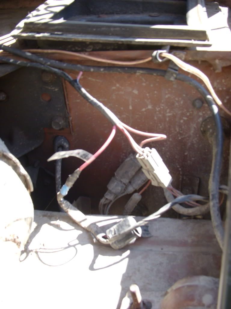
A little no on the harness coming out of the drivers side. Out of this harness there are 5 wires. Two (white/red & red/white) go to the water temp & oil pressure sensors. One is the Red w/ green stripe wire that is on the same line as the brown wire from the I post on the starter relay (continuity check) that is just cut and goes to nothing. Then there is a blue wire & the Red w/ blue stripe wire in a cannon plug. Blue wire ones to nothing & red/blue goes to coil.
Sorry for so much info, but I'm not just looking for a "replace the relay" answer. I've put tons of hours into researching this and getting everything straightened out and am looking for someone who really understands the charging system and correct wiring.
I greatly appreciate any help and can take pics in the morning and am also willing to talk to someone over the phone if it helps.
John
I bought my 77 bronco from a Buddy who did the 3G upgrade /old regulator removal. He also installed a new coil and distributor.
First I have a 130a 3G alternator and I'm only getting about 6-7 volts off the back of it at idle. It doesn't seem to be charging my battery as when the Truck is running the most volts i'm getting at the battery is maybe 11 I've replaced it three times so now I'm pretty sure it's not a bad alternator.
Second, sometimes my bronco won't turn off. I've replaced relay 4 times and now went to solid top post style, ignition switch and starter. It will run fine for a week or a day and then Wham it just won't stop. Today it happened to my son and it killed the battery really quick. When I pulled the I post wire off it seemed to "reset" itself and is now working fine again.
It's almost a viscous circle in the fact that this then kills the battery when I come out to start the bronco, which could be part of my charging problems.
Now the wiring. I have never seen the old regulator as the 3G is internally regulated.
I'll start with starter relay (top post new style napa #STH404)
B Terminal, 0 ga wire to battery, yellow wire from harness, black w/ yellow stripe (fusible link) from harness & black w/ red stripe (fusible link) from harness (both the black wires are about 10-12 ga and go to the same plug with a yellow wire that is going down to the "I" terminal on the alternator.
M Terminal, 0ga wire going to starter.
I Terminal, brown wire from harness ( wiring diagram says this ties into a Red w/ green stripe wire hat goes to coil, but.... On the drivers side coming out of the cab is a Red w/ green stripe wire just cut off. This wire is on the same line as the brown wire as verified by a onto unity check - see below under coil).
S Terminal, Red w/ blue stripe from harness (this goes to back of ignition switch)
All these "harness" wires o through the firewall on the passenger side into the cab.
Alternator, pretty self explanatory.
B+ Terminal, 0ga wire goes to starter relay B
A Terminal, yellow/white wire goes to Alt B+
S Terminal, white/black wire goes to spade on Alt
I Terminal, this wire goes to a yellow wire that is in the same under/connector as the two thicker black wires on the relay B terminal.
Battery
0ga wire from + to starter relay B Terminal
0ga wire from - to frame, I also have a 0ga wire going from frame to block on both sides of engine.
Coil
Positive side has two wires.
One wire goes to distributor
Other wire is going to a Red w/ blue stripe wire that comes out of the drivers side firewall. This wire goes to the back of the ignition and is the same wire (continuity checks out) as the wire on the "S" terminal of the starter relay.
Negative side has one wire going to distributor.
A little no on the harness coming out of the drivers side. Out of this harness there are 5 wires. Two (white/red & red/white) go to the water temp & oil pressure sensors. One is the Red w/ green stripe wire that is on the same line as the brown wire from the I post on the starter relay (continuity check) that is just cut and goes to nothing. Then there is a blue wire & the Red w/ blue stripe wire in a cannon plug. Blue wire ones to nothing & red/blue goes to coil.
Sorry for so much info, but I'm not just looking for a "replace the relay" answer. I've put tons of hours into researching this and getting everything straightened out and am looking for someone who really understands the charging system and correct wiring.
I greatly appreciate any help and can take pics in the morning and am also willing to talk to someone over the phone if it helps.
John
Last edited: