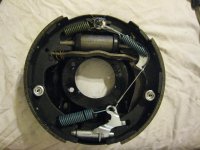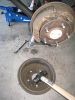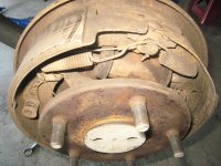









• Welcome to ClassicBroncos! - You are currently viewing the forums as a GUEST. To take advantage of all the site features, please take a moment to register. It's fast, simple and absolutely free. So please join our community today!
    If you have problems registering or can't log into your account, please contact Admin.

Rear 9" Drum Assembly

ILikeBond

Sr. Member
Joined
Jan 27, 2009
Messages
908
I'm refurbishing my rear drums as part of my build (especially since I busted one drum removing it with a sledge%)). I have a '74 with a medium duty large bearing rear axle, which means the somewhat unusual 10" drums. Because of this, I couldn't find a pre-assembled drum kit, but had to purchase the WildHorses drum brake master kit, which is self-assembly. The Ford 9" drums are notoriously complex, and while I found some decent reference diagrams and a helpful YouTube video showing the assembled drum, I wasn't able to find a good quality, simple step-by-step guide to assembly.

Because of that, I decided to document my assembly and post it here. But another reason is, I'm sure for some of you--unlike me--this is very basic stuff. Brakes are kinda important :p, and while I think I've done this correctly, I'm partially posting this for feedback in case I muffed something up. So, please, if you see something wrong, please tell me so I can fix it before I kill myself or someone else out on the street!

On the other hand, if everything looks copacetic, let me know that too, as it'll give me confidence to run these as assembled.
 
OP
OP
ILikeBond

ILikeBond

Sr. Member
Joined
Jan 27, 2009
Messages
908
First Steps

I disassembled my rear 9", saving all the parts in large ziplock bags even though I planned to buy all new drums. This was a good decision, as I only determined after receiving the WH Drum Brake Master Kit that there were 4 parts per side that I needed to retain from my old setup. More on that later.

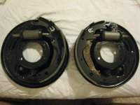
I began by soaking my backing plates in carb cleaner for a couple days, then in Evapo Rust Remover from Harbor Freight. This stuff is biodegradable, non-toxic, and easily disposable (down the sink), but works like magic on rust. Highly recommended! Here's what the plates looked like after that process.

IMG_1767.jpg

After some research, I've decided to paint my frame and undercarriage with Chassis Saver, which is like an easier-to-use version of POR 15. This presented the perfect opportunity to give it a first go. Here's what one looked like after finishing one side.

IMG_1770.jpg IMG_1772.jpg

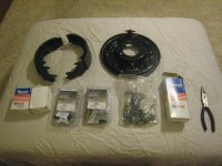
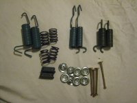
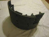
After painting both side of both drums and allowing a couple days to fully cure, I was ready to begin assembly. Here's what came in the WH kit I ordered - (1) two new wheel cylinders (L/R specific), (2) two self-adjusting kits (L/R specific - 2nd photo), (3) the spring kit (both sides, not L/R specific - 3rd photo), and (4) the shoes. I also ordered new drums from WH, not pictured.

IMG_1784.jpg IMG_1787.jpg IMG_1918.jpg

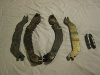
Not included in the WH kit, and pieces I needed to retain from the old brakes were (1) parking brake links, (2) parking brake link springs (not pictured), (3) parking brake levers, and (4) wheel cylinder pins. The picture is after some cleanup.

IMG_1902.jpg
 
OP
OP
ILikeBond

ILikeBond

Sr. Member
Joined
Jan 27, 2009
Messages
908
Assembly 1

Note that the wheel cylinders, self-adjusting kits, parking brake link, and parking brake lever are all side-specific, while the remaining parts are interchangeable. Be sure to match side-specific parts.

I assembled the left brake first, which took a couple hours, then the right brake, which took far less time after doing the first one. Photos, however, will be interspersed and/or show both sides.

(1) Place wheel cylinder pins snugly inside wheel cylinder. Insert wheel cylinder into backing plate, and secure with two 5/8" bolts on rear side of backing plate.

IMG_1791.jpg IMG_1793.jpg IMG_1802.jpg IMG_1914.jpg

(2) Shoes come in a set with a primary and secondary shoe. The secondary shoe has a smaller brake surface by a few inches and will house most the moving parts. Place the correct-side parking brake lever through the secondary shoe from the back and secure with the horseshoe clip that comes with the spring kit.

IMG_1906.jpg IMG_1916.jpg IMG_1915.jpg

(3) The shoes can now be placed on the backing plate and secured. The secondary shoe should go on the left of the right brake, and vice versa.
IMG_1928.jpg
 
OP
OP
ILikeBond

ILikeBond

Sr. Member
Joined
Jan 27, 2009
Messages
908
Assembly 2

(4) The shoes must be secured with the hold-down spring provided in the spring kit. This is one of the most difficult assembly tasks. While I think there are some specifically-designed tools to make this easier, I used needle nose pliers, which sucked and took a lot of failures before success, but I have some tips.

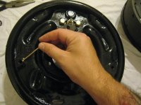
(4a) Insert hold-down spring nail through the hole in the center-outside of the rear of the backing plate, and thread through third hole down from the top of the shoe.

IMG_1929.jpg IMG_1930.jpg

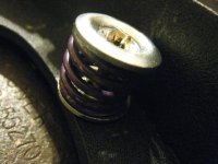
(4b) Place one hold-down spring plate over hold-down spring nail, cup-side up, then spring, then second hold-down spring plate over spring, cup-side down. I found it was much easier to compress the spring after conditioning them for a while with zip ties.

IMG_1931.jpg IMG_1932.jpg IMG_1933.jpg IMG_1943.jpg

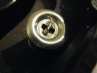
(4c) Using needle-nose pliers, push assembly over hold-down spring nail and rotate so that nail is perpendicular to slot in hold-down spring plate. This will take some time and frustration. The rear of the backing plate is concave, so it will help if you place something (a magnet, piece of metal, or piece of wood) directly below the nail head to prevent up-and-down slop. You want the nail to remain as straight and high as possible to make securing the top hold-down spring plate as easy as possible.

IMG_1941.jpg IMG_1942.jpg IMG_1938.jpg

This should be done on both sides, then the wheel cylinder's pins fitted over the cut-out in each shoe.

IMG_1953.jpg
 
Last edited:
OP
OP
ILikeBond

ILikeBond

Sr. Member
Joined
Jan 27, 2009
Messages
908
Assembly 3

(5) Place the parking brake link in the second set of cut-outs on the shoes from the top, with the parking brake link spring fitted over the longer set of tines, which goes to the primary shoe. The short tines should fit over the valley in the parking brake lever, not the secondary shoe. Be sure the curve in the parking brake link curves over the opening in the backing plate for the axle.

IMG_1954.jpg

(6) Place the half-moon assembly (actuating cable guide) in the second hole from the top of the secondary brake shoe, and the self-adjuster leveler in the large hole at the bottom of the secondary brake shoe (second hole from bottom), with the guide (e.g., hole) oriented up.

IMG_1958.jpg

(7) Place the end cap over the end of the adjuster screw assembly and insert both ends over the respective portions of the shoe, at the bottom. The self-adjuster leveler should rest on top of the adjuster screw assembly.

IMG_1959.jpg IMG_1961.jpg

(8) Place the actuating cable over the anchor pin. Don't worry about the cable for now, just orient it generally downward.

IMG_1962.jpg

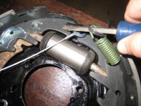
(9) Now its time to place the springs. These are very tight/strong and require some leverage to get in place. Start with the short, medium-thick spring that runs from the top hole on the primary shoe to the anchor pin. Next, run the long, thin spring from the half-moon adjuster cable guide to the anchor pin. Finally, run the short thick spring from the large hole at the bottom of the primary shoe (second from bottom), to the self adjuster leveler guide. For the first two springs, I used a flat head screwdriver to get leverage, which I first slipped through a zip tie to pull the spring down on the screwdriver. I was able to pull the bottom spring over the self adjuster leveler guide with just a pair of needle nose pliers (much easier than the first two springs).

IMG_1964.jpg IMG_1969.jpg IMG_1983.jpg

(10) Place the "hook" on the actuating cable over the self adjuster leveler guide. Now all that needs to happen is for the cable to run around the half-moon adjuster cable guide. This will take some leverage, which I was able to generate using two flat head screwdrivers, similar to placing a bicycle tire over a rim.

IMG_1970.jpg IMG_1994.jpg

(11) Finally, place a brake adjusting hole cover (supplied in both the spring kit and self-adjusting kits) in each hole on the rear of the backing plate.

IMG_2001.jpg IMG_2005.jpg
 
Last edited:
OP
OP
ILikeBond

ILikeBond

Sr. Member
Joined
Jan 27, 2009
Messages
908
Finished Product

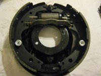
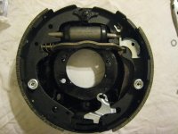
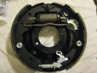
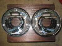
So here's the finished product, left and right. What do you think, did I do everything right?

Hope this will be helpful to someone at some point. :cool:

IMG_2007.jpg

Bond/Jack
 

DuctTape

Bronco Guru
Joined
Jun 20, 2008
Messages
1,148
Loc.
Bozeman, MT
Looks right to me!

Just FYI, while I invested in a shop manual off eBay, quite a lot of the diagrams can be found be using google images. I still think the shop manuals were a good investment, btw.
 

needabronco

Bronco Guru
Joined
Jul 2, 2004
Messages
6,411
Loc.
Prescott/Farmington
As always I highly suggest that anyone tackling a job they are not familiar with, especially drum brakes, take a few digital pictures of them before they take anything apart, and only do one side at at time so you can see if you missed something.

But yes it looks right (from memory)
 

Viperwolf1

Contributor
electron whisperer
Joined
Aug 23, 2007
Messages
24,451
Sorry to be the bearer of bad news but you have the primary and secondary shoes backwards. Primary lining is smaller and goes toward front. Secondary lining does the braking after the primary shoe pushes against it.
 

Timmy390

Contributor
Bronco Guru
Joined
Jan 1, 2011
Messages
5,948
Loc.
Conway, AR
Looks right to me!

Just FYI, while I invested in a shop manual off eBay, quite a lot of the diagrams can be found be using google images. I still think the shop manuals were a good investment, btw.

I LOVE my Haynes manual. Well worth the money and then some.

Tim
 

redtail

Sr. Member
Joined
Jul 14, 2010
Messages
621
Hey, why are you doing this in the house? it's almost mandatory you do this in the cold shop on your knees under the bronco cursing the little springs as they spring back at you when they slip off the pliers ;D

looks good though.
 
OP
OP
ILikeBond

ILikeBond

Sr. Member
Joined
Jan 27, 2009
Messages
908
As always I highly suggest that anyone tackling a job they are not familiar with, especially drum brakes, take a few digital pictures of them before they take anything apart, and only do one side at at time so you can see if you missed something.

Agreed. I did this, and it helped (although I didn't do them one at a time, I disassembled both and bagged them a few weeks before assemblying the new parts).

Looks right. but can you hook up the E-brake cables with all that assembled?

I thought about that. I ordered a new cable set from WH, which I think is a little different than the stock cables, and from what I could tell eyeballing it, there should be room to insert them. If not, I can remove the bottom spring and get some play in the shoes without needing to take apart the whole assembly. So I'll cross that bridge when I come to it, but I appreciate the head's up.


Sorry to be the bearer of bad news but you have the primary and secondary shoes backwards. Primary lining is smaller and goes toward front. Secondary lining does the braking after the primary shoe pushes against it.

No, I appreciate it, but everyone else said it looks OK, and it looks like the diagrams, so... maybe you're looking at them backwards? (e.g., thinking the left is right and vice versa). Anyway, I'll double check this when I mock them up.

Can anyone else confirm or deny this statement?

Hey, why are you doing this in the house? it's almost mandatory you do this in the cold shop on your knees under the bronco cursing the little springs as they spring back at you when they slip off the pliers ;D

So I could take pictures on my wife's nice white sheets of course! :p Don't tell her... ;)
 

Rustytruck

Bronco Guru
Joined
Feb 24, 2002
Messages
10,872
One of the things you forgot to note is there is suppose to be grease applied to the backing plate where the shoes rub. the adjuster screws should be disassembled and the threads greased and grease applied under the cap. Grease was factory applied where 2 pieces are assembled like the pivots for the parking brake. under the spring cups where they go up against the shoes. under the brake apreader bars and the wheel cylinder pins where they push against the shoes.
The factory used a grease called lubriplate. Use eithor this stuff or marine wheel bearing grease will do. Failure to grease these parts causes rust and wear on the backing plates. Without grease the brakes will also tend to pull and grab untill the brakes get fully loaded causing the Bronco dip and dive action when you first apply the brakes.

You are doing great keep up the good work. All the years on this site no one has tackled writing up this stuff Good For You!
 

Viperwolf1

Contributor
electron whisperer
Joined
Aug 23, 2007
Messages
24,451
No, I appreciate it, but everyone else said it looks OK, and it looks like the diagrams, so... maybe you're looking at them backwards? (e.g., thinking the left is right and vice versa). Anyway, I'll double check this when I mock them up.

I don't know what diagrams you're using but they are wrong. Same is true for anyone that says they look ok.
 

Attachments

  • Bronco 835.jpg
    Bronco 835.jpg
    79.3 KB · Views: 257
OP
OP
ILikeBond

ILikeBond

Sr. Member
Joined
Jan 27, 2009
Messages
908
Grrr! :-X

Looking back at my tear-off pictures, I think Viperwolf is right - I muffed the placement of the primary and secondary shoes. Here are a few photos from the right (passenger) side disassembly. The short shoe is in the front, whereas on my photos above, the short shoe is on the rear of the right drum. !@#$%

IMG_1444.jpg IMG_1445.jpg IMG_1448.jpg IMG_1450.jpg IMG_1452.jpg

Can't believe I screwed this up. Now I have to do all the hard stuff over (springs off and on). ARGH!

I don't suppose there's any chance I can get away with just switching them around (e.g., placing R drum assembly on driver side)? This would affect the orientation of the brake line, of course, but I imagine it could be bent slightly without an issue. But I'm guessing it would affect the e-brake and maybe other things, and this is probably wishful thinking, right? %)
 
OP
OP
ILikeBond

ILikeBond

Sr. Member
Joined
Jan 27, 2009
Messages
908
You guys beat me to it. Yep, I screwed up. <sigh> Thanks for that diagram, Viperwolf. It wasn't one I had found...
 

Viperwolf1

Contributor
electron whisperer
Joined
Aug 23, 2007
Messages
24,451
I don't suppose there's any chance I can get away with just switching them around (e.g., placing R drum assembly on driver side)? This would affect the orientation of the brake line, of course, but I imagine it could be bent slightly without an issue. But I'm guessing it would affect the e-brake and maybe other things, and this is probably wishful thinking, right? %)

No chance. Do it right for safety and shoe life. It's easier if the backing plate is bolted to the axle.
 
Top