|
Several years ago, I installed a 2 ˝” suspension lift on my mostly stock '70 Bronco. The lift turned out very well, and I was very pleased with myself. It completely changed the way my Bronco looked, and I was proud to drive it down the street. So proud, in fact, that I could completely ignore the newly created vibration in the suspension. For a while, anyway… For the last year however, that vibration has become more irritating, since by then, I was pretty sure what caused it. In my Bronco, the vibration started around 40 mph. and continued through 65 mph. or so, which is as fast as I ever seem to drive my Bronco.
The reason for the vibration was the increase in the pinion angle from installing the suspension lift. The term "pinion angle" is generally considered to be the difference, expressed in degrees, between the centerline of the pinion gear in the rear differential, and the centerline of the driveshaft. The increase in pinion angle is due to the suspension lift raising the frame and drivetrain, including the transfer case, and not the rear differential. Since the transfer case end of the driveshaft is now several inches higher, the angle between the driveshaft and the pinion gear is increased.
Normal, or stock pinion angle, is somewhere around 1-1 ˝ °. As the pinion angle increases past 3-4°, the u-joint will experience increased wear and possible premature failure. As the pinion angle increases past 9-10°, the vibration I experienced will be felt, along with the increased wear on the u-joint.
Here's a picture showing the rear yoke and driveshaft. You can see with your eyes how much of a difference there is.
So, now that I knew what the problem was, what were my options for fixing it. One option could be to remove the rear differential, cut off the spring perches, rotate the differential to obtain the proper pinion angle, and then re-weld the spring perches back on. But I wasn't too happy with that option. That seemed like more work than necessary, and, I don't own a welder.
Another option is to install some tapered shims between the leaf springs and the spring perches. This would wind up rotating the rear differential housing, and it's a simple bolt-on. This seems like the best choice.
Now that I had decided on installing the shims, I needed to determine what angle shims to install. This would involve measuring the current pinion angle. I did search on Google for “measure pinion angle”, and had a listing of more technical articles that I could read in a lifetime.
There are two methods for measuring the pinion angle. The first method uses an angle measuring gauge (adjustable protractor) to measure the difference between the pinion flange and the drive shaft directly. These gauges are available for under $10 from a hardware store. Place the edge of the gauge vertically against the front of the pinion flange, beside the driveshaft. Extend the measuring arm forward parallel to the bottom of the driveshaft. Extend a straight edge under the driveshaft to the measuring arm of the angle gauge. Hold the straight edge flat against the bottom of the driveshaft and adjust the measuring arm to read the angle. Depending on the gauge you use, you may have to subtract 90° from your reading to get the correct number.
The second method measures the angle, from horizontal, of the driveshaft and pinion shaft separately, then comparing the two. You can use a gravity angle gauge (available at hardware stores) to do the measuring. I happened to already have a machinists level, which seemed to work just fine.
My first step was to measure the angle of the driveshaft. Just lay the angle finder or, in my case, the level, along the length of the driveshaft. Adjust the angle until the bubble is centered, then note the angle. For me, the angle was 18 ˝° from horizontal.
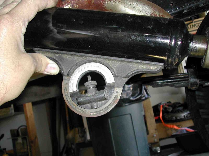
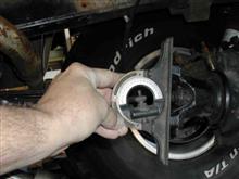
Next, measure the pinion gear centerline angle. Since you can't really get to the pinion gear shaft, the acceptable thing to do is to measure the angle of something at 90° from the pinion shaft, and add (or subtract) 90° from that reading. I chose to measure across the face of the yoke, so I removed the two u-joint u-bolts and moved the driveshaft out of the way. Then placed the level across the face of the yoke, and took my measurement. This turned out to be 8°. So, the difference between the driveshaft angle and the pinion shaft angle is 10 ˝°. Looks like I need some correction!
When determining what degree shims to buy, remember that installing shims rotates the differential, which will raise the yoke relative to the transfer case. This changes the driveshaft angle, which ultimately reduces the pinion angle. I wanted to wind up with about 2° of pinion angle when I was done. With my current 10 ˝° pinion angle, I would have been inclined to order 8° shims. But, after thinking about the yoke moving up, lessening the driveshaft angle, I decided to order 6° shims.
In doing some research on installing rear axle shims, I constantly came across recommendations to NOT use aluminum shims, especially cast aluminum. It seems they have a tendency to deform over time, and, on occasion, crack and fall out. This leaves the rear differential loose on the springs. I ran across a company in California, 4Crawler Offroad, that custom makes several items for off-road vehicles, including steel axle shims. I can't say enough good things about 4Crawler Offroad and their web site. Not only do they offer quality products for sale, but, as an example, in the section on shims, provides and explanation of the shims and what they do, how to measure for shims, how to install shims, FAQ, etc. If you can't tell, this company impressed me. Find them at http://www.4crawler.com/4x4/ForSale/Shims.shtml.
The shims I ordered were a stock size, 4 Ľ” by 2 ˝” by 6°. I placed the order through the web site and had the shims in just a couple days. Here's a picture of the received shims.
Now that I've got the shims, I need to install them. First step is to jack up the Bronco and support it by the frame, then remove the wheels to aid access to the axle u-bolts. Here's a picture of how I manage to get a little extra height out of my 4 ton jack stands.
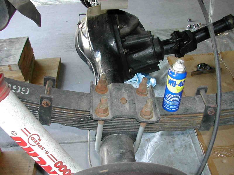
Support one side of the differential with a floor jack. Although the pictures don't show it, my jack is under the brake drum. Remove one end of the shock so it doesn't limit the droop of the differential when you remove the u-bolts. I'm still running the stock rear shock mounts, and it was easier to remove the top of the shock. Some type of penetrating oil is always a good idea on these types of projects.
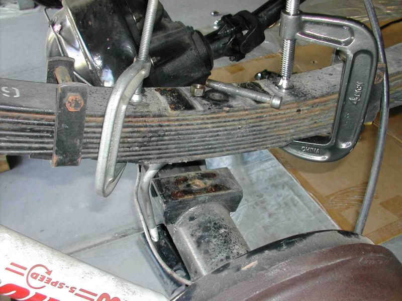
Remove the u-bolts and spring retainer. Position a c-clamp on each end of the lower leaf and tighten, to hold the spring pack together when removing the leaf spring bolt.
Lower this end of the differential, and use whatever type of persuasion is necessary, until the leaf spring bolt comes loose from the spring perch. Remove the leaf spring bolt. Here's a picture of the removed leaf spring bolt, for anyone who hasn't seen one before. Note the round head to fit the hole in the spring perch.
My 6° shims are about Ľ” thick where the spring bolt goes through. I got lucky and had an extra Ľ” of thread left on my spring bolt. If you don't have enough bolt thread left, you will have to buy new, longer spring bolts. Measure the original bolt carefully, as the replacement spring bolts come in different size heads, as well as lengths. Insert the spring bolt through the correct side of the shim, slide back through the spring pack, and tighten up the nut. These shims are made with a relief on one side so the spring bolt head has a surface that's parallel to the spring. This way the spring bolt head won't get cocked to one side as it's tightened.
Jack up the differential, making sure the spring bolt head gets fully inserted into the spring perch. Reassembly is pretty much the opposite of disassembly. Finish up one side, then on to the other side. Total time to install the shims, from jacking up the Bronco to cleaning and putting away my tools was only 3 hours, including time to take pictures. Here's a picture of the installed shim.
I got everything back together and took a final measurement of the pinion angle. I was happy to find that I wound up with a 2° pinion angle. Of course I had to take it for a ride and was amazed to find how smooth it drove. All the vibrations I'd been living with for the past several years was gone. This project was a big success!!!
Tech article by
70_Steve
|