• Welcome to ClassicBroncos! - You are currently viewing the forums as a GUEST. To take advantage of all the site features, please take a moment to register. It's fast, simple and absolutely free. So please join our community today!
    If you have problems registering or can't log into your account, please contact Admin.

Ammeter and starter solenoid question

joshnjulie1

Sr. Member
Joined
Jul 11, 2012
Messages
891
Loc.
Moreno Valley, Ca
Need some expert (I'll take what I can get) advise.

I just need to know if this is possible and if I am chasing the right rabbit.

I accidentally sparked the battery wire that runs through the ammeter gauge.

Now she won't start.

When I removed the starter solenoid (becasue that was where the wire ran to) the damn thing is rattling like something is busted lose inside.

?-Could me sparking that wire in turn result in blowing something in the solenoid therfore a good enough reason why she won't start. I have looked at and replaced eveything else along the way and this is the last thing I am left with thinking it could be.

--Installed new Centech wire harness, etc.
Thanks guys.
 

70_Steve

Old Guy
Joined
Dec 13, 2002
Messages
8,317
Need some expert (I'll take what I can get) advise.

I just need to know if this is possible and if I am chasing the right rabbit.

I accidentally sparked the battery wire that runs through the ammeter gauge.

Now she won't start.

When I removed the starter solenoid (becasue that was where the wire ran to) the damn thing is rattling like something is busted lose inside.

?-Could me sparking that wire in turn result in blowing something in the solenoid therfore a good enough reason why she won't start. I have looked at and replaced eveything else along the way and this is the last thing I am left with thinking it could be.

--Installed new Centech wire harness, etc.
Thanks guys.
Fro me it's probably the "take what you can get" advice. I have a Centech manual on my PC at work, but didn't copy it to my home PC...

One big question. Do you have headlights?

The stock wiring harness has a "loop", from the + battery cable connected at the starter solenoid, into the cabin behind the dash where all the connections for power to the Bronco are made, through the ammeter, and back to the output of the alternator. At the starter soleniod the connection to that loop is made through a fuseable link. So... all the power to the stock Bronco electrical system goes through this link. Blow the link (sparking the wire at the ammeter) and nothing get power, includiing the headlights which get power directly from the "loop".

So, if you don't even have headlights, look for the Centech equivalent of that fuseable link.

For the starter solenoid.... Remove it. Connect the mounting tabs to the negative side of the battery and connect the STA terminal (little terminal next to the big BAT+ terminal) and see if it clicks. It's just a relay, with one side of the coil connected to the STA terminal, and the other side of the coil connected to the mounting tabs or flange... HINT - The starter solenoid won't work unless that flange is grounded. This is normally done by mounting it to the fenderwell.
 

70_Steve

Old Guy
Joined
Dec 13, 2002
Messages
8,317
I have headlights... that's as much info as I can muster right now. I'm lost.
You're doing fine.

So, if you have headlights, and the Centech has the equivalent of a fuseable link, you do have power to the "loop". If you turn the key to ON, do you have any other 'stuff' powered? Blinkers, horn, heater fan motor, etc? If so, then maybe focus on the starter solenoid.

Do you have a voltmeter, and if so, do you know how to use it?
 
OP
OP
joshnjulie1

joshnjulie1

Sr. Member
Joined
Jul 11, 2012
Messages
891
Loc.
Moreno Valley, Ca
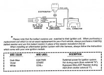
All gauges, cluster lights, heater all work fine. I just cannot get spark to the coil. I have the Centech harness with points and have it hooked up according to their directiosn using the resistor ballast. I have a new chepo coil, starter solenoid, ignition switch.

Turns over great, just no spark and fire. It's something simple I'm sure but am at my wits end now.
 

70_Steve

Old Guy
Joined
Dec 13, 2002
Messages
8,317

Attachments

  • Centech Points Wiring.jpg
    Centech Points Wiring.jpg
    94.2 KB · Views: 26
OP
OP
joshnjulie1

joshnjulie1

Sr. Member
Joined
Jul 11, 2012
Messages
891
Loc.
Moreno Valley, Ca
I keep seeing 'point wire' from distributor, but mine has two wires, one red one black. I have the red on the + and the black on the -.

That is exactly how I have it hooked up as long as it doesn't matter the wire type going from the ballast to the coil. I ran short of wire and used a cut off section of a 'start' violet wire to run that section.

I have not replaced the VR though. That seems to be the only thing left. Would this cause anything I am missing? Appreciate the quick responses, I am in the garage now trying to figure this thing out. It has been a couple of weekends so far...
 

70_Steve

Old Guy
Joined
Dec 13, 2002
Messages
8,317
Do you have a voltmeter, and if so, do you know how to use it?

Still need an answer!!!
Third time's a charm!!!??


Remove the distributor cap and find out where the wires connect. Red wire to the points maybe? Black wire to the housing of the distributor, maybe?

I suspect having them both connected to the coil is wrong, although I don't remember (not that I'm the most aware guy) a distributor with two wires. The current path is through the ballast resistor (or bypass wire) to the + side of the coil. Then through the coil from the - side to the distributor. The points in the distributor ground the current and makes the spark.
 
OP
OP
joshnjulie1

joshnjulie1

Sr. Member
Joined
Jul 11, 2012
Messages
891
Loc.
Moreno Valley, Ca
Sorry didn't even realize the question. I do have a meter and am at beginner level of using it.

Opening the distributor I have a Pertronix Ignitor. Website says the black goes to the - and the red goes the beginning of the ballast... oh man. I'm getting the fire extinguisher out.
 

70_Steve

Old Guy
Joined
Dec 13, 2002
Messages
8,317
Sorry didn't even realize the question. I do have a meter and am at beginner level of using it.
OK, good!!! So now I'll go back to another previous question.


If you have a voltmeter and know how to use it, I'd ask whether, with the key ON, do you have voltage on the + side of the coil. Measure from the + side of the coil to a known good ground.

You will want to have the meter on a DC Volts scale. Most meters now have a 20 VDC scale. To make sure you're using the voltmeter correctly, measure the voltage on your battery, and make sure you are able to read somewhere around 12.5 Vdc.

If you are successfull at that, turn the key to ON and measure the voltage from the + side of the coil to a good ground, like the negative side of the battery. Might also want to use the engine as a ground also, and compare the readings.

Edit: looked up the Pertonics Ignitor instructions on the web and that all looks OK.
 
OP
OP
joshnjulie1

joshnjulie1

Sr. Member
Joined
Jul 11, 2012
Messages
891
Loc.
Moreno Valley, Ca
I got a little over 12v from the battery and the same reading from a ground to the positive side of the coil with the key on.

That Pertonix Ignitor thing in the distributor.. Does that mean I do not have 'points' then since they were removed to put the ignitor in? Also, then does that mean I do or do not need the ballast resistor?
 

70_Steve

Old Guy
Joined
Dec 13, 2002
Messages
8,317
I got a little over 12v from the battery and the same reading from a ground to the positive side of the coil with the key on.

That Pertonix Ignitor thing in the distributor.. Does that mean I do not have 'points' then since they were removed to put the ignitor in? Also, then does that mean I do or do not need the ballast resistor?
You do not have 'points'. The Pertronics Ignitor is a replacement for points.

The coil is what determines whether you need a ballast resistor or not. Most coils, even the high performance ones, need a ballast resistor. Without that resistor, the coil will get too hot and be damaged.

With the distributor cap off, turn the key to START, and watch the rotor inside the distributor, to make sure it turns.

If the rotor turns, I'd be suspect of the Pertronics module.There is a Tech Line number in the instructions. http://www.pertronix.com/support/manuals/pdf/ignitor12vneg.pdf

Just reread your posts. Your Pertronics should be wired up as in Figure 3 in the instructions above. That is, the Pertronics Red wire should be on the Centech Blue wire side of the ballast resistor, not the coil+ side.

I can't remember, as I write this, if this Bronco has run since you got it. If it did, what happened between the time it ran and now?
 
OP
OP
joshnjulie1

joshnjulie1

Sr. Member
Joined
Jul 11, 2012
Messages
891
Loc.
Moreno Valley, Ca
It did run when I got. All this is happening after I replaced the wiring with a Centech so the problems could be endless. I will do what you mentioned above. Thank you.
 

70_Steve

Old Guy
Joined
Dec 13, 2002
Messages
8,317
It did run when I got. All this is happening after I replaced the wiring with a Centech so the problems could be endless. I will do what you mentioned above. Thank you.
You may have seemingly endless problems with the harness ( ;) ) but this problem is pretty straight-forward. You've verified a big part of the possibilities, in that you have 12 volts to the + side of the coil with the key ON. That all the farther the harness is involved.

Try moving the RED Pertronics wire to the other side of the ballast resistor and see what happens. I seem to remember the Pertronics are particularly sensitive to reduced voltages. S'matter of fact, I believe there are a couple entries in the Pertronics Q&A about "Reduced Voltages".

And... Here they are!!

Q. The engine will not start or runs rough. Are there any tests that I can do?
A. Yes, remove the red Ignitor™ wire from the coil positive terminal. Connect a jumper wire from
the positive side of the battery directly to the red Ignitor™ wire. If the engine starts and runs
well, you may have a low voltage problem. Remember this is just a test and not intended for
permanent installation. Read “ How to correct a low voltage poblem”

Q. How to correct a low voltage problem?
A. First, if you have an external ballast resistor, connect the red Ignitor™ wire to the ignition wire
prior to the ballast resistor. Second, if you do not have a ballast resistor you must locate a 12
volt source that is controlled by the ignition switch to connect the red Ignitor™ wire to.
 
OP
OP
joshnjulie1

joshnjulie1

Sr. Member
Joined
Jul 11, 2012
Messages
891
Loc.
Moreno Valley, Ca
With everything hooked up according to plan and with 12v to the + side of the coil, I am now at the conclusion that the Pertronix Ignitor I has taken a crap on me. I am half tempted to purchase the points and condensor, put a new cap and rotor, plug wires in and make sure I have it wired up correctly according to those instructions and see what happens. That seems to me an inexpensive test to try and pinpoint what is going on.

What's your take?
 

70_Steve

Old Guy
Joined
Dec 13, 2002
Messages
8,317
With everything hooked up according to plan and with 12v to the + side of the coil, I am now at the conclusion that the Pertronix Ignitor I has taken a crap on me. I am half tempted to purchase the points and condensor, put a new cap and rotor, plug wires in and make sure I have it wired up correctly according to those instructions and see what happens. That seems to me an inexpensive test to try and pinpoint what is going on.

What's your take?
Well that is an option. I might not be inclined to replace cap and wires at this point only because of the number of problems I've seen caused by miswiring the cap and wires. But you're right. A new set of points is an inexpensive troubleshooting tool. Also not bad just for trail spares if you do ever get the Pertronics going.

Same thing happened to me quite a few years ago. I did a conversion on my ex-wife's 72 Chebby Nova, and used a Mallory kit. Ran great for about a year, then it started intermittantly dying. Finally, to help troubleshoot, I installed the old points and never had another problem. Sold the car 10 year later and it still had the points in it.
 
OP
OP
joshnjulie1

joshnjulie1

Sr. Member
Joined
Jul 11, 2012
Messages
891
Loc.
Moreno Valley, Ca
Running through some diagnosis, and this is what I have a concern about;

With the key on, using my light tester, I have power at both the + terminal of the coil and the - terminal of the coil.

Is this right, and if not would my Pertronix Ignitor be the cause since the black wire is connected to the - and the red connected to the + of the coil?

Thanks again.
 
OP
OP
joshnjulie1

joshnjulie1

Sr. Member
Joined
Jul 11, 2012
Messages
891
Loc.
Moreno Valley, Ca
I forgot to add that I also have the same power on both terminals of the coil when it is cranking. I sure hope I'm on the right track thinking it could be the Pertronix Ignitor.

I just can't figure out if it is the 'points' or in my case the PI that supplies spark to the coil which is hopefully why I'm not getting any damn spark from the coil.
 

70_Steve

Old Guy
Joined
Dec 13, 2002
Messages
8,317
I forgot to add that I also have the same power on both terminals of the coil when it is cranking. I sure hope I'm on the right track thinking it could be the Pertronix Ignitor.

I just can't figure out if it is the 'points' or in my case the PI that supplies spark to the coil which is hopefully why I'm not getting any damn spark from the coil.
It would make sense that the voltage would stay the same on both sides of the coil if the points, or whatever was allowing current flow through the coil, was not working.

The spark is created by a collapsing magnetic field inside the coil. The coil is basically a transformer, with a primary and secondary winding. The primary winding is just a few turns of heavy wire, and is the high voltage connection to the distributor. The secondary winding is thousands of turns of a small gauge wire connected to the + and - terminals of the coil. Both are wound around the same core.

The current path would be from the ignition switch, through the ballast resistor to the + side of the coil. Then out the - side of the coil to the points. The points are just a simple switch. When closed, they allow current to flow through the coil to ground. When open the current flow stops.

Voltage is generated when a conductor passes through a magnetic field. And it doesn't make any difference if it's the conductor that's moving or the magnetic field.

When there is current flow through the secondary winding of the coil (points closed) a magnetic field is created. The lines of flux grow, but slowly (relatively speaking). Then when the points open the current flow is interupted, and the magnetic field collapses. It's just kinda the way things work, that a magnetic field will collapse many, many times faster than it will grow. It's that collapsing magnetic field that generated the high voltage in the primary winding and you see a spark.

The Pertronics Ignitor takes the place of the points. So instead of a mechanical switch (points), the Ignitor is an electronic switch.

It does look like the Ignitor, for whatever reason, isn't working.
 
Last edited:
OP
OP
joshnjulie1

joshnjulie1

Sr. Member
Joined
Jul 11, 2012
Messages
891
Loc.
Moreno Valley, Ca
I will double check the test of a pulsing light/voltage form the - sid efo the coil to ground. If I don't get the pulsing like I think I should, I will start with the PI as my culprit. I really do appreciate all the help Steve. I feel like I am getting dumber by the day as I try and figure out what is wrong with this thing.
 
Top