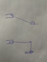
@ksagis Yes, you are missing something.
Your "crappy drawing" is missing the bending moment component. The offset linkage creates exactly the same side force at the HB input.
A correct force diagram would include a bending moment component in the push rod. Which means that the push rod is not just pushing. It's pushing and loading sideways thru bending. (very much like an offset tie rod end.)
The HB input sees exactly the same side load in each scenario. Ironically, if I were making a Free Body diagram of the force load of the offset linkage at the HB input...I would use the axially loaded diagram.
The ONLY reason to use an offset linkage is to allow for moving the HB up or down relative to the fender/hood. You will find that offset HB inputs are drop in replacements for offset input vacuum boosters with large diameter diaphragms. When engineered without the vacuum booster constraint...the input rod is straight.
I would post a sketch, but I let my contributor status expire. Send an e-mail to
jamesroney@yahoo.com, and I can send you a sketch.
But the sideways force component in either scenario is the sine of the angle times the axial force. For small angles, the axial force approximates the horizontal force. (which is the pedal effort times pedal ratio)
You can convince yourself of this by exaggerating your drawing. Just keep going to 45 degrees, and then past 60 degrees up to 90 degrees. Eventually, 100% of the force ends up as side load.
Gotta run...


