Here you go, been using this document I found on line across a few Explorer installs.... Doug
(Sorry I had to cut and paste, Classic said it didn't recognize my Word doc)
| Ford Explorer Camshaft Position Sensor | |
1996 Ford Explorer AWD
5.0 liter V-8
Fuel injection
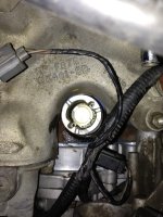
A. The Camshaft Position Sensor (CMP) could very well be the source of the noise. It is much like a distributor without the cap and rotor.
Here is how to replace it. You will need a special tool to do it however.
REMOVAL:
CAUTION: Syncro Positioning Tool T96T-12200-A must be obtained prior to installation of the replacement synchronizer assembly. Failure to follow this procedure will result in the fuel system being out of time with the engine, possibly causing engine damage.
CAUTION: Prior to the removal of the Camshaft Position (CMP) sensor, set No.1 cylinder to 0 degrees Top Dead Center (TDC) of compression stroke. Then note the position of the CMP sensor electrical connector. The installation procedure requires that the electrical connector be located in the same position.
Disconnect battery ground cable.
NOTE: When battery voltage is removed from the Powertrain Control Module (PCM), all learned values will be cleared and reset to predetermined values. When battery voltage is restored to the PCM, the vehicle may exhibit certain drivability concerns. It will be necessary to drive the vehicle to allow the PCM to relearn values for optimum drivability and performance. assembly and repeat Step 5.
1. Disconnect fuel charging wiring electrical connector from CMP sensor.
Remove the CMP sensor screws and sensor from camshaft synchronizer.
CAUTION: Do not move crankshaft until entire installation procedure is complete. Doing so will result in the fuel system being out of time with the engine resulting in possible emissions fault.
NOTE: If camshaft synchronizer is to be removed from the cylinder block, proceed with Step 4 If the camshaft synchronizer is not being removed, proceed to Installation Step 8 assembly and repeat Step 5.
Remove hold-down clamp.
Remove camshaft synchronizer from cylinder block.
Camshaft Synchronizer
INSTALLATION:
Attach Syncro Positioning Tool T96T-12200-A.
Align the synchronizer vane with the radial slot of the Syncro Positioning Tool T96T-12200A.
Rotate the tool on the synchronizer base until the tool's boss engages the base notch.
Dip gear end into ESE-M2C123-A oil or equivalent to coat gear, thrust washer and lower bearing.
CAUTION: Do not rotate crankshaft when Syncro positioning tool is on the camshaft synchronizer. Armature tab will be damaged and synchronizer timing may be shifted.
Install camshaft synchronizer into cylinder block making sure that arrow on Syncro Positioning Tool T96T-12200-A is pointing forward parallel to center line of crankshaft. This step will locate camshaft position sensor electrical connector to the pre-removal position.
Syncro Positioning Tool
CAUTION: If camshaft position sensor electrical connector is not positioned properly, DO NOT reposition the connector by rotating the synchronizer assembly. This will result in the fuel system being out of time with the engine, possibly causing engine damage. Remove the synchronizer assembly and repeat Step 5.
Install hold-down clamp and tighten to 23-34 Nm (17-25 lb ft).
Remove Syncro Positioning Tool.
Install CMP sensor and CMP sensor screws. Tighten to 2.5-3.5 Nm (23-30 lb in).
Connect fuel charging wiring electrical connector to camshaft position sensor (CMP sensor).
Connect battery ground cable.