• Welcome to ClassicBroncos! - You are currently viewing the forums as a GUEST. To take advantage of all the site features, please take a moment to register. It's fast, simple and absolutely free. So please join our community today!
    If you have problems registering or can't log into your account, please contact Admin.

5.0 Explorer Motor Wiring with Waste-Spark Coils : "Quick way", with minimal harness changes.

yakelys69

Sr. Member
Joined
Nov 20, 2006
Messages
756
This thread is a spin off rom the "Windsor 5.0 Explorer Motor Wiring with Waste-Spark Coils" in the chat section. Im starting this to help Moddz67 on his installation, hopefully this will be a step by step thread with minimal rabit holes.

Moddz67 is starting with kit 550-1316 "HOLLEY EFI TERMINATOR X MAX - 2V FORD MOD MOTOR"

5.0 Explorer Motor Wiring with Waste-Spark Coils & 4R70W/75W 98+ trans​

550-1316 kit
* 554-153 Term X Max
* 558-108 Main Engine Harness
* 558-314 Ignition Harness
* 558-209 Injector Harness
* 558-470 Trans Harness

5.0 Explorer Motor Wiring with Waste-Spark Coils & manual transmission​

550-1216 kit
* 558-108 Main Engine Harness
* 558-314 Ignition Harness
* 558-209 Injector Harness


Using the Holley site if you search for each part number individually for the most part you can get the diagrams for that harness. In this case the 558-314 Ignition Harness is included in the 558-108 Main Engine Harness diagram.

The reason to use this kit 550-1316 (or alternatively the 550-1216 if you have a manual transmission) is that it includes the coil drivers needed to make the waisted spark coil packs work. The modular engine used dumb coils rather than smart coils. Smart coils have the coil driver integrated in the coil itself.

It's possible to get this setup to work with 2 wire crank and cam sensors, I don't recommend it, n my opinion and limited experience you will waist hours and it will be unreliable.

To get started you will need a 3 wire crank and cam sensor.

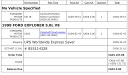
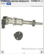
For the cam sensor the solution I used was to purchase a ford cam synchronizer & sensor for 98 5.0 Explorer. The old explorers had 3 wire sensors.
Note: You can't just change the sensor (top) as the synchronizer is different (according to my notes) Also for whatever its worth upto 2008 on the ford 6 cylinder 4.2 the sensor is the same but the synchronizer is a different length.

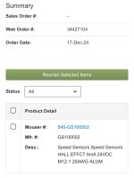
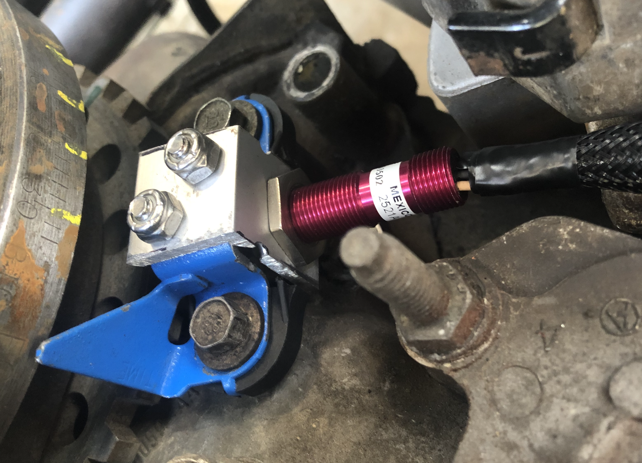
For the Crank sensor you need to obtain a three wire sensor and find a way to mount it, kits probably exist from megasquirt or something but i never looked into it. Holley sells one but I dont know much about that. What I did was Purchase a "Cherry - Gs100502 - Geartooth Hall Effect Sensor." Now it's a "ZF Gs100502". (Part number: ZF Gs100502 or Gs100502 )

I cut the bolt ears off the ford pickup to keep the spacing, then attached an aluminum l bracket to keep the pickup in the stock ford location and retain the timing pointer. paying attention to the clearance from the instructions on the new pickup. Just used whatever was on my bench at the time. Perhaps welding a ridged metal bracket would have also worked fine. See img
cherry-crank.png
 
Last edited:
OP
OP
yakelys69

yakelys69

Sr. Member
Joined
Nov 20, 2006
Messages
756
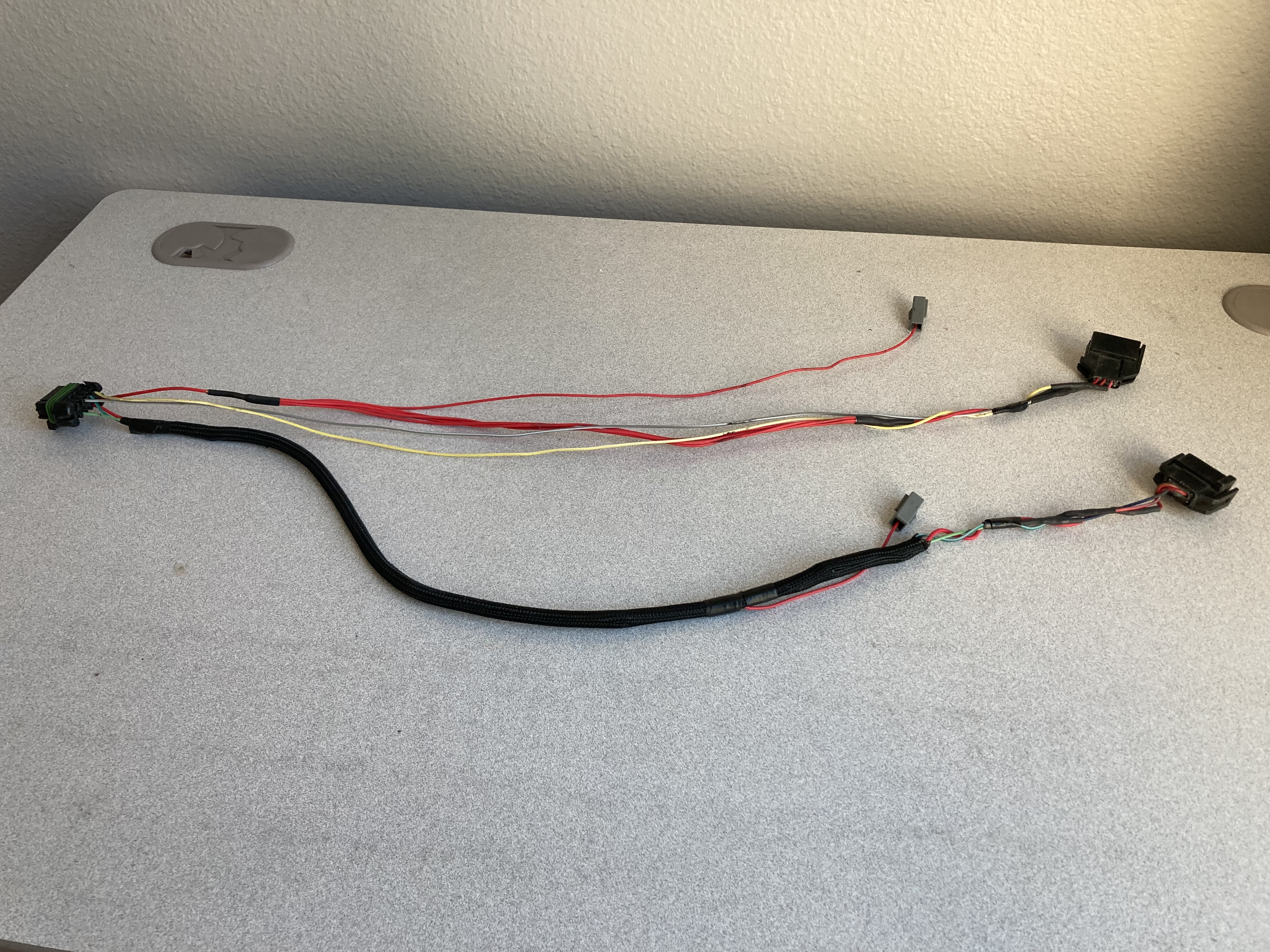
Step 1: 558-314 Ignition Harness

Do to revisions of diagrams and inconsistencies, you will need to know how to use a voltmeter and do a continuity test. If you don't it's simple just do some internet searches. However, since we will only be modifying one harness and one pin the labeled wires should be adequate to reference.

Waisted spark only needs one Holley coil driver (4 per block), these kits come with two blocks. For the "Quick Way" we will use both Holley coil drivers wired as they are from Holley.

This is the worst part of the process
Fot the ignition harness 558-314 you will need to splice in the ford connectors, the center pin is power, the little capacitors you may have one or two, those are also supplied power and the harness includes those connectors.

Remove & discard the wires for CYL 4, 5, 6, 8

Create two branches
Driver Side Coil Pack [1 & 6, 3 & 5]
- Use one of the capacitor connectors for capacitor
- Use Cyl 3 B22 Gray/White
- Use one of the positive leads for your center connector.
- Use Cyl 1 B21 Yellow/white

Passenger Side Coil Pack
- Use one of the capacitor connectors for capacitor
- Use Cyl 7 B24 Light Green/White
- Use one of the positive leads for your center connector.
- Use Cyl 2 B15 Green/White

Once Done
558-314-modified.jpg


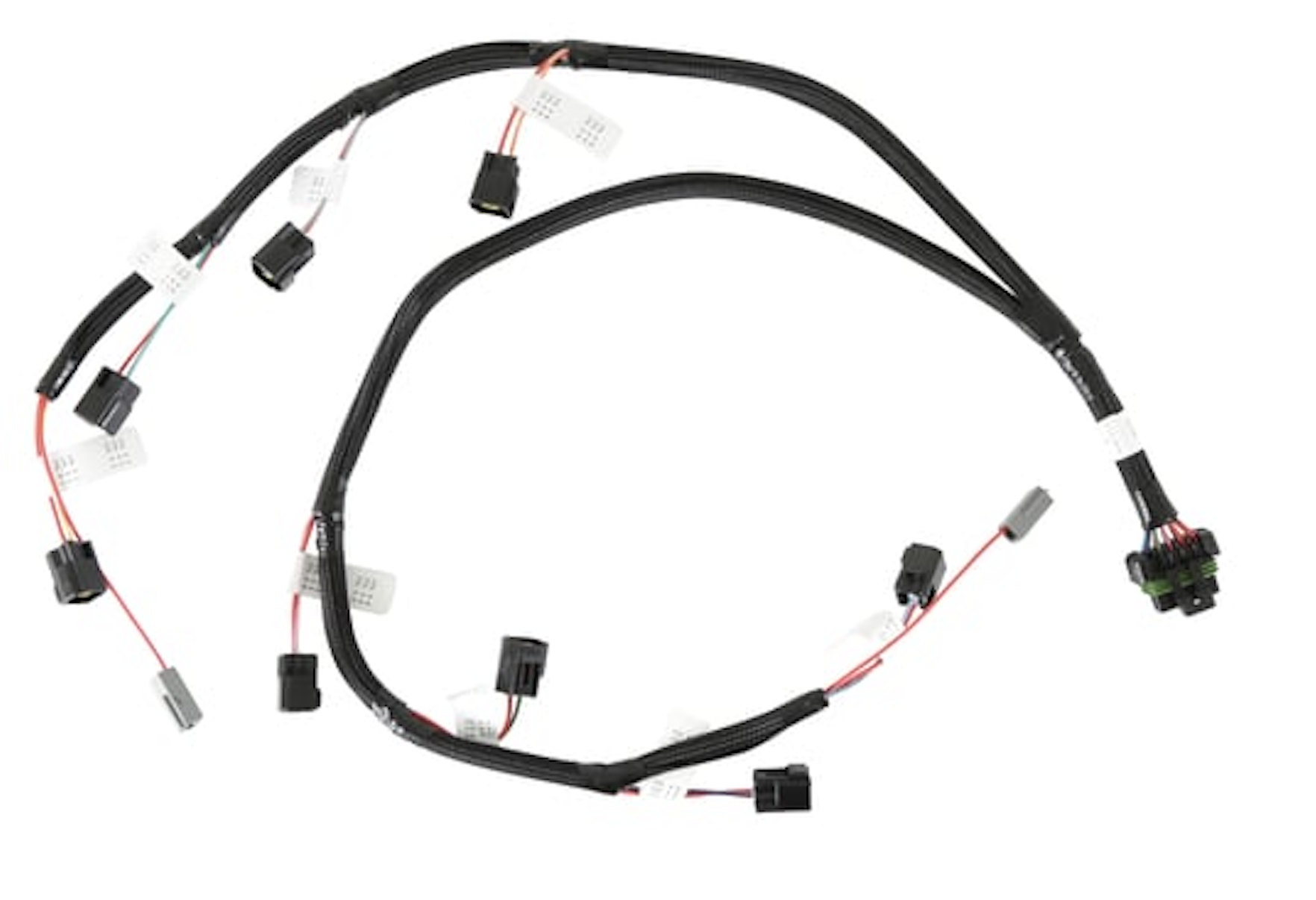
Original
558-314-orig.png
 
Last edited:

Moddz67

Contributor
New Member
Joined
May 22, 2024
Messages
15
This thread is a spin off rom the "Windsor 5.0 Explorer Motor Wiring with Waste-Spark Coils" in the chat section. Im starting this to help Moddz67 on his installation, hopefully this will be a step by step thread with minimal rabit holes.

Moddz67 is starting with kit 550-1316 "HOLLEY EFI TERMINATOR X MAX - 2V FORD MOD MOTOR"

This includes
550-1316 kit
* 554-153 Term X Max
* 558-108 Main Engine Harness
* 558-314 Ignition Harness
* 558-209 Injector Harness
* 558-470 Trans Harness

Using the Holley site if you search for each part number individually for the most part you can get the diagrams for that harness. In this case the 558-314 Ignition Harness is included in the 558-108 Main Engine Harness diagram.

The reason to use this kit 550-1316 (or alternatively the 550-1216 if you have a manual transmission) is that it includes the coil drivers needed to make the waisted spark coil packs work. The modular engine used dumb coils rather than smart coils. Smart coils have the coil driver integrated in the coil itself.

It's possible to get this setup to work with 2 wire crank and cam sensors, I don't recommend it, n my opinion and limited experience you will waist hours and it will be unreliable.

To get started you will need a 3 wire crank and cam sensor.

For the cam sensor the solution I used was to purchase a ford cam synchronizer & sensor for 98 5.0 Explorer. The old explorers had 3 wire sensors.
Note: You can't just change the sensor (top) as the synchronizer is different (according to my notes) Also for whatever its worth upto 2008 on the ford 6 cylinder 4.2 the sensor is the same but the synchronizer is a different length.

For the Crank sensor you need to obtain a three wire sensor and find a way to mount it, kits probably exist from megasquirt or something but i never looked into it. Holley sells one but I dont know much about that. What I did was Purchase a "Cherry - Gs100502 - Geartooth Hall Effect Sensor." Now it's a "ZF Gs100502". (Part number: ZF Gs100502 or Gs100502 )

I cut the bolt ears off the ford pickup to keep the spacing, then attached an aluminum l bracket to keep the pickup in the stock ford location and retain the timing pointer. paying attention to the clearance from the instructions on the new pickup. Just used whatever was on my bench at the time. Perhaps welding a ridged metal bracket would have also worked fine. See img
cherry-crank.png
Ok I have ordered the parts listed as required.
 

Attachments

  • IMG_7429.jpeg
    IMG_7429.jpeg
    171.2 KB · Views: 6
  • IMG_7430.jpeg
    IMG_7430.jpeg
    137.2 KB · Views: 5
  • IMG_7431.jpeg
    IMG_7431.jpeg
    178.9 KB · Views: 5

Moddz67

Contributor
New Member
Joined
May 22, 2024
Messages
15
This thread is a spin off rom the "Windsor 5.0 Explorer Motor Wiring with Waste-Spark Coils" in the chat section. Im starting this to help Moddz67 on his installation, hopefully this will be a step by step thread with minimal rabit holes.

Moddz67 is starting with kit 550-1316 "HOLLEY EFI TERMINATOR X MAX - 2V FORD MOD MOTOR"

This includes
550-1316 kit
* 554-153 Term X Max
* 558-108 Main Engine Harness
* 558-314 Ignition Harness
* 558-209 Injector Harness
* 558-470 Trans Harness

Using the Holley site if you search for each part number individually for the most part you can get the diagrams for that harness. In this case the 558-314 Ignition Harness is included in the 558-108 Main Engine Harness diagram.

The reason to use this kit 550-1316 (or alternatively the 550-1216 if you have a manual transmission) is that it includes the coil drivers needed to make the waisted spark coil packs work. The modular engine used dumb coils rather than smart coils. Smart coils have the coil driver integrated in the coil itself.

It's possible to get this setup to work with 2 wire crank and cam sensors, I don't recommend it, n my opinion and limited experience you will waist hours and it will be unreliable.

To get started you will need a 3 wire crank and cam sensor.

For the cam sensor the solution I used was to purchase a ford cam synchronizer & sensor for 98 5.0 Explorer. The old explorers had 3 wire sensors.
Note: You can't just change the sensor (top) as the synchronizer is different (according to my notes) Also for whatever its worth upto 2008 on the ford 6 cylinder 4.2 the sensor is the same but the synchronizer is a different length.

For the Crank sensor you need to obtain a three wire sensor and find a way to mount it, kits probably exist from megasquirt or something but i never looked into it. Holley sells one but I dont know much about that. What I did was Purchase a "Cherry - Gs100502 - Geartooth Hall Effect Sensor." Now it's a "ZF Gs100502". (Part number: ZF Gs100502 or Gs100502 )

I cut the bolt ears off the ford pickup to keep the spacing, then attached an aluminum l bracket to keep the pickup in the stock ford location and retain the timing pointer. paying attention to the clearance from the instructions on the new pickup. Just used whatever was on my bench at the time. Perhaps welding a ridged metal bracket would have also worked fine. See img
cherry-crank.png
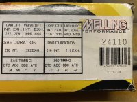
Not sure if this changes much but I also purchased this camshaft a while back to replace the factory 86 5.0L HO cam.
 

Attachments

  • IMG_7433.jpeg
    IMG_7433.jpeg
    193.4 KB · Views: 7
OP
OP
yakelys69

yakelys69

Sr. Member
Joined
Nov 20, 2006
Messages
756
Cam will come in later but I think you may have an issue with the gear on the cam sync.
Melling M-Select Class 1 Camshafts 24110 is made from chilled cast iron and requires a composite or bronze distributor gear. Examples are listed below.

COMP Cams Composite Distributor Gears 35200
PRW Bronze Distributor Gears 0730201

someone else will know this better and hopefully advise.
 

nvrstuk

Contributor
Just a Bronco driver for over 50 yrs!
Joined
Jul 31, 2001
Messages
9,234
Thanks for doing this yakelys69... I was going to but a couple of ya know what's keeping from it. That said, Holley is WAAAAY behind on their wiring diagrams as I found 3 with mistakes and they (Holley) agreed that they were inaccurate and might not ever upgrade them since it's been so long! Wait- really???

That said, from your first post I just want to let people know that Holley has screwed up. I think I wrote the info down on my build thread and if & when I get a chance I'll try to find the ones I remember aren't correct. Just a bummer that we need those to help us and they don't care- admitting it.

Once again- I"m just doing a heads up that several of the Holley wiring diagrams are not accurate.
 

nvrstuk

Contributor
Just a Bronco driver for over 50 yrs!
Joined
Jul 31, 2001
Messages
9,234
Step 1: 558-314 Ignition Harness

Do to revisions of diagrams and inconsistencies, you will need to know how to use a voltmeter and do a continuity test. If you don't it's simple just do some internet searches.

Waisted spark only needs one Holley coil driver (4 per block), those kits come with two blocks. Awesome you have a hot spare. From the ECU to the Ford Coil Packs will look like this


PAUSE : I will edit this post once I update my diagram and photos.
Good thing to mention because if you call Holley Tech and ask them ANY question about wiring or not running properly or other questions then the tech line guys WILL SAY YOU NEED TWO OF THE HOLLEY COIL DRIVERS to make your engine run! Which you don't. Soooo frustrating, so ignore Holley tech and come here if you can get your answers quickly enough- hope so.

I had a couple issues and fought the Holley Tech help because only ONE guy there know's Holley Term X and Fords very well at all. I have his name written down and will also try to post it up for you. Also, the BIG NAME company I bought mine from had promised to help get it running as part of the purchase of the Term X. He knew absolutely nothing about Wasted Spark and had everything screwed up. I mean everything- beyond frustrating when you are a complete novice and are trusting the guy (that you think might be doing something wrong) but can't figure it out (being a complete novice) so you are flailing in the mud bog not making progress.
 

Moddz67

Contributor
New Member
Joined
May 22, 2024
Messages
15
Cam will come in later but I think you may have an issue with the gear on the cam sync.
Melling M-Select Class 1 Camshafts 24110 is made from chilled cast iron and requires a composite or bronze distributor gear. Examples are listed below.

COMP Cams Composite Distributor Gears 35200
PRW Bronze Distributor Gears 0730201

someone else will know this better and hopefully advise.
So can I get one of those gears and swap it for the one on the sync.?
 

nvrstuk

Contributor
Just a Bronco driver for over 50 yrs!
Joined
Jul 31, 2001
Messages
9,234
Yes you can. Typical Ford issue is compatibility with cam sync and distr shaft sizes and the roll pin diameter and location do not always interchange. Yeah, not kidding!

Ford does this to keep Hot Rodders from wanting to build anything with "Ford" on the grill or title. :( Frustrating but just be patient and look at Ford Motorsports website (I believe that's the one) which will show the correct depth for the bottom of the cam gear and make sure it's spot on- believe it's on my build thread) or Yakelys and others will know if the majority of the cam gears for the 5.0's are the correct shaft dia and roll pin location.) ??

My .02 and anybody that's run a bronze gear on a street rig is this- don't do it not matter how much $ you're saving. Bronze is soft and it will wear out quickly leaving bronze material throughout your engine (bearings come to mind). Spend the money on the Comp Cams Composite gear as they are "one & done" will last forever. Bronze works for 1/4 milers since they pull the engine apart with maybe a hundred miles on it. Not worth it.
 
OP
OP
yakelys69

yakelys69

Sr. Member
Joined
Nov 20, 2006
Messages
756
Hi Moddz67, Im going to do this thread as the "Quick way", with minimal harness changes. If later you want to do the "Minimal harness" way I will be posting a thread on that later.

I did the "Quick way" first and as Im documenting am doing it the "Minimal harness" way. Anyway Im going to have two threads, just deciding what one this is.s
 
Last edited:

dmoses42

Contributor
Bronco addict
Joined
Jan 25, 2017
Messages
475
Loc.
Brunswick, Ga
Hi Moddz67, Im going to do this thread as the "Quick way", with minimal harness changes. If later you want to do the "Minimal harness" way I will be posting a thread on that later.

I did the "Quick way" first and as Im documenting am doing it the "Minimal harness" way. Anyway Im going to have two threads, just deciding what one this is.s
So, I'm following this. By "minimal harness" do you mean you will be shortening the wires, or removing wires?
 
OP
OP
yakelys69

yakelys69

Sr. Member
Joined
Nov 20, 2006
Messages
756
So, I'm following this. By "minimal harness" do you mean you will be shortening the wires, or removing wires?
Both, I don't think I'll be able to do a step by step, but will document my process and concepts. Just like always stock wire harnesses are a crazy birds nest under the loom.
 

dmoses42

Contributor
Bronco addict
Joined
Jan 25, 2017
Messages
475
Loc.
Brunswick, Ga
Both, I don't think I'll be able to do a step by step, but will document my process and concepts. Just like always stock wire harnesses are a crazy birds nest under the loom.
Ok, I guess I'll just follow both when you start the other one. Thanks for your effort. I modified a harness following EFI Guy's videos during the COVID lockdown, but it was for another Bronco, and now he can't do non-egr without an old block to work from so now this seems easier. More expensive, but easier. Maybe.
 
Top