• Welcome to ClassicBroncos! - You are currently viewing the forums as a GUEST. To take advantage of all the site features, please take a moment to register. It's fast, simple and absolutely free. So please join our community today!
    If you have problems registering or can't log into your account, please contact Admin.

Battery Ground to block location

ntsqd

heratic car camper
Joined
Jan 30, 2005
Messages
3,391
Loc.
Upper SoKA
I've spent way more time at work chasing down EMI/RFI gremlins than I've ever wanted to. Reducing and eliminating it is a black art, don't let an EE tell you different. There is some science to it, but there are no hard and fast rules. What works for one situation doesn't always work for any others.

Just because Ford did it one way doesn't mean that their way will always work. Change one simple thing, intentionally or not, and you've changed the situation enough that the previous approach may or may not continue to work. My approach has yet to fail me or any situation that I've applied it to. I choose not to invite trouble, it finds me well enough on it's own.
 

brianstrange

Bronco Guru
Joined
Nov 22, 2011
Messages
1,626
"an over-sized lug from the depot, over the insulated wire. ... Sharpen the lug screw a bit to penetrate and secure the wire, and you're done."
That's not a very secure or reliable connection. It's better to solder a simple Copper tab to a short stripped section, just like the later trucks have.

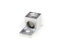
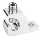
A:It is secure if you size it properly. The screw cant have much of a point, but they work quite well. You are correct that a soldered joint would be better, but midpoint terminals are not easy to find (locally anyway) The ideal "Home Depot" part would be a clamping style lug, and strip a small section of lug. These two have held well


"Also, NEVER ground electronics etc... to the battery."
Why not? That's where everything goes eventually, anyway.

A: Because if you have a main ground failure, it will fry electronics connected that way. It's rare, but it happens, especially on boats.


The Battery terminals will never lose function because they are stainless as well.

I don't think they're stainless, but regardless - battery acid will eat stainless, and DOES attack those newer clamps.
Good to know, thanks!. I was assuming they were a top quality stainless, I have yet to have them fail. I have had top quality conventional ones last 2-3 years in the rust belt.


Ugh! sorry about the poor color choice, I'm even worse trying to multi-quote
 

Attachments

  • slug1.jpg
    slug1.jpg
    19.8 KB · Views: 28
  • slug2.jpg
    slug2.jpg
    31.3 KB · Views: 28
Last edited:

Steve83

Bronco Guru
Joined
Jul 16, 2003
Messages
9,041
Loc.
Memphis, TN, USA, Earth, Milky Way
The screw cant have much of a point, but they work quite well.
The lugs in your pictures are NOT for automotive use, OR for penetrating insulation. They're only for solid wire, or heavy (stationary) strands; not fine automotive strands.
...midpoint terminals are not easy to find (locally anyway)
But they're easy to make from common plumbing Copper which IS easy to find anywhere, and easy to work. Have you looked at that factory one? It's nothing more than a scrap of Copper (tinned) and wrapped around the main cable before soldering.
The ideal "Home Depot" part would be a clamping style lug, and strip a small section...
HD doesn't sell anything suited to this application, other than Copper tubing & hangers to cut a solder terminal from.
Because if you have a main ground failure, it will fry electronics connected that way.
Misusing a residential wiring terminal is a really good way to increase your chances of having a main ground failure. And if the main ground fails, it'll probably take all the sensitive electronics out, no matter how their grounds were connected.
I have had top quality conventional ones last 2-3 years in the rust belt.
I don't understand why you think they're top-quality if they only last 3 years. I have MANY original-equipment battery terminals still working after decades of abuse & neglect. You could too, with a little more maintenance since you know you live where corrosion is common.
 

brianstrange

Bronco Guru
Joined
Nov 22, 2011
Messages
1,626
The lugs in your pictures are NOT for automotive use, OR for penetrating insulation. They're only for solid wire, or heavy (stationary) strands; not fine automotive strands.But they're easy to make from common plumbing Copper which IS easy to find anywhere, and easy to work. Have you looked at that factory one? It's nothing more than a scrap of Copper (tinned) and wrapped around the main cable before soldering.HD doesn't sell anything suited to this application, other than Copper tubing & hangers to cut a solder terminal from.Misusing a residential wiring terminal is a really good way to increase your chances of having a main ground failure. And if the main ground fails, it'll probably take all the sensitive electronics out, no matter how their grounds were connected.I don't understand why you think they're top-quality if they only last 3 years. I have MANY original-equipment battery terminals still working after decades of abuse & neglect. You could too, with a little more maintenance since you know you live where corrosion is common.

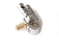
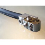
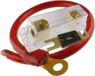
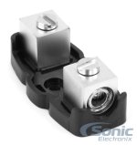
I have had very good experiences with the terminals above, especially the one on the left. Many of the "Higher end" power blocks hold up well with a screw in lug just fine. I have one in service on my 67 Mustang for over 10 years, and it's holding up, no sign of failure or corrosion. The reason Auto manufacturers don't use them is a combination of service life and cost. Dispute it all you want, but it works properly. I wasn't referring to the other battery cables as top quality, just reference to what the manufacturers call them. Perhaps I need to be use quotes so my communication is better.

Many of the automotive grade components are much cheaper than industrial (and in some cases residential) wiring products. Automotive grade in many cases = cheap. For the others that are following, These have had proven results. Here are some examples of a screw down terminal will offer a tight bond to fine wire. Have a great day folks!
 

Attachments

  • connector 1.jpg
    connector 1.jpg
    105.8 KB · Views: 25
  • connector2.jpg
    connector2.jpg
    28.5 KB · Views: 22
  • fuse1.jpg
    fuse1.jpg
    30.5 KB · Views: 19
  • fuse2.jpg
    fuse2.jpg
    65 KB · Views: 18

ntsqd

heratic car camper
Joined
Jan 30, 2005
Messages
3,391
Loc.
Upper SoKA
I understand the appeal of screw-down connectors, but I do not trust them in an automotive application. While the initial electrical conductivity is good, the conductor's strand ends are left exposed and are subject to corrosion being able to migrate up inside of the conductor's insulation. Living in this Coastal Desert I get to experience corrosion at an advanced rate so that likely makes me hypersensitive to it. Probably doesn't help that my previous position was designing sub sea electrical connectors for ROV's and submersibles.

Properly crimped lugs are far superior IF the lugs used are closed-end, the crimping tool used does a correct job, and adhesive lined heat-shrink is used to cover the small gap between the insulation and the lug's body. A correct crimp squeezes all of the copper to the point that cutting thru the middle of the crimp and polishing that end won't reveal any boundary lines or air gaps between the elements. An acid wash will be needed to see them with the naked eye.

However, the correct crimp also does not cause the assembly to extrude, to grow longer in the crimp zone. This is a very fine line, the crimping tool that you hit with a hammer isn't going to produce a correct crimp. If the crimp extrudes the copper in the crimp zone then it had been excessively work hardened and is more likely to fail from fatigue.

My source for this info is a former co-worker/Supervisor whom Boeing paid his Reference Engineer's salary for several years to do an investigation into crimping and what constitutes a good vs bad crimp. He was not against soldering, but industry as a whole is turning away from soldering lugs and terminals onto cables. Partly for speed of assembly, partly because of the skill required to not cause the solder to wick up the cables or wires.
 

brianstrange

Bronco Guru
Joined
Nov 22, 2011
Messages
1,626
My source for this info is a former co-worker/Supervisor whom Boeing paid his Reference Engineer's salary for several years to do an investigation into crimping and what constitutes a good vs bad crimp. He was not against soldering, but industry as a whole is turning away from soldering lugs and terminals onto cables. Partly for speed of assembly, partly because of the skill required to not cause the solder to wick up the cables or wires.

Did the person from Boeing mention anything about the wires breaking at solder joints? One of our contract engineers (Aerospace Electrical) mentioned that proper solder splices are stronger at the actual joint, but the wire becomes more brittle at the solder endpoint. I still use solder\heat shrink for splices, but would think twice about doing so in a wire assembly that has movement.
 

ntsqd

heratic car camper
Joined
Jan 30, 2005
Messages
3,391
Loc.
Upper SoKA
IF the solder is contained within the connector then it is no different than a properly crimped connection. It is considerably harder to do that than it is to get a proper crimp and requires a person with significant skill to do it. I know that I can't repeatedly do it, so I crimp.

I think that my source (now at Eaton) would contest the notion that a soldered joint is stronger than a properly executed crimp. He didn't seem to think so.
 

brianstrange

Bronco Guru
Joined
Nov 22, 2011
Messages
1,626
IF the solder is contained within the connector then it is no different than a properly crimped connection. It is considerably harder to do that than it is to get a proper crimp and requires a person with significant skill to do it. I know that I can't repeatedly do it, so I crimp.

I think that my source (now at Eaton) would contest the notion that a soldered joint is stronger than a properly executed crimp. He didn't seem to think so.

He was referring to a pure solder\heat shrink splice (not using a connector) vs. a pure crimp connector (using a connector) He explained the solder bonding itself is stronger, but it weakens the wires on either side. My view is we're probably talking unlikely odds if both are done well, but as the wire gets thinner, I'd worry more about soldering.
 

Steve83

Bronco Guru
Joined
Jul 16, 2003
Messages
9,041
Loc.
Memphis, TN, USA, Earth, Milky Way
Automotive terminals are DIFFERENT from industrial & residential. I'm familiar with all 3. Using the wrong one WILL give the impression that it was "weak" or "cheap", but that's just a function of its MISapplication.

The fact that you've gotten away with it for a long time only proves that you know more about what you're doing than the typical grease monkey or vehicle owner. Not that it's a good idea, or particularly suited to that application.

Anything can be done wrong, so a bad solder joint can be just as bad as a bad crimp joint. But it's easier (particularly with heavy cables of fine strands) for an inexperienced person to get a good (enough) solder joint than a good crimp. I just did one of the worst ones I've ever done a few days ago (because the owner didn't have the cash to buy new cable, and it's just a beater mud-truck), and it was still strong enough to lift the battery off the tray. It also made an immediate & profound improvement in the starter performance.

Since automotive stranded cable uses fine strands, and they're always slightly slack (as compared to industrial heavy strands that are usually tensioned), I can't imagine how long it would take for a typical 4ga battery cable to fail from stress-concentration due to solder. And based on my observations, it just doesn't happen within the lifetime of the vehicle & its battery cables. Smaller wires are even less-stressed mechanically, so they're even less-likely to exhibit that kind of failure. There are quite a few small solder joints in my CV that are doing fine after a decade or so of hard driving.

. . .

A few of them were crimped, but I soldered most of them. All of these were soldered, and the guy I shipped this engine & wiring harness to has never complained about failed joints:

. . . .

That was at least 12 years ago.
 

dave67fd

Bronco Guru
Joined
Sep 24, 2010
Messages
2,863
Seeing as we are writing books on this thread, here's mine;D

There has always been a debate on crimp vs soldering..Either is acceptable if executed properly with the correct tools but they both carry their advantages and disadvantages. Some Industry applications may and do only use one or the other and never both. You wouldn't ever solder an Ethernet cable to connector would you?

Nowadays, generally speaking and depending on the Industry, crimping is considered the norm. It is quicker and generaly easier (time is money) than soldering and requires less tools/materials.

A person who is well trained in soldering may not be able to make a proper mechanical crimp and vise versa so again the connection is only as good as the person performing the task. So my solder connection may be more effective than your crimp.

Typically, automotive connections use crimp connections mainly due to high mechanical stress (vibration), temperature variations and chemical resistance. Most if not all soldering applications used in high stress environments (i.e..automotive, aerospace etc..) is typically protected/contained for weather resistance, vibration etc. or by other means such as coating/potting.

The important aspects to remember when using the correct connector for the job is that it is of the proper current carrying capacity, the correct material for ajoining connections and properly protected from excess stress, chemicals etc..Connector types are usually designed specific to the industry it is intended but does not mean it wont properly work or be effective for another.

An improper crimp (or solder connection) can have a higher level of resistance which can and will cause havoc especially in higher current applications.

The debate on which joint is stronger again goes back to the installer and the quality of the work and materials used.
Using either process and properly done in both instances the wire should break first and not the crimp or solder connection. If I was doing both I would barely shy towards the solder connection being the strongest and I have done both with nearly every type of connection and variation known to man.

In the aspect of making connections direct to the battery (in a simple circuit scenario) it will depend on the type of load. If you have a high current device it is prefered to hit the battery directly as most factory automotive wiring is not rated for it. When using lower power/sensitive electronic devices it's not recommended. It is a non-regulated source and typically introduces excess amounts of noise from the charging system.

And please don't get me started on the RF noise debate, I could probably write a trilogy on it.
 

brianstrange

Bronco Guru
Joined
Nov 22, 2011
Messages
1,626
Seeing as we are writing books on this thread, here's mine;D

There has always been a debate on crimp vs soldering..Either is acceptable if executed properly with the correct tools but they both carry their advantages and disadvantages. Some Industry applications may and do only use one or the other and never both. You wouldn't ever solder an Ethernet cable to connector would you?

Nowadays, generally speaking and depending on the Industry, crimping is considered the norm. It is quicker and generaly easier (time is money) than soldering and requires less tools/materials.

A person who is well trained in soldering may not be able to make a proper mechanical crimp and vise versa so again the connection is only as good as the person performing the task. So my solder connection may be more effective than your crimp.

Typically, automotive connections use crimp connections mainly due to high mechanical stress (vibration), temperature variations and chemical resistance. Most if not all soldering applications used in high stress environments (i.e..automotive, aerospace etc..) is typically protected/contained for weather resistance, vibration etc. or by other means such as coating/potting.

The important aspects to remember when using the correct connector for the job is that it is of the proper current carrying capacity, the correct material for ajoining connections and properly protected from excess stress, chemicals etc..Connector types are usually designed specific to the industry it is intended but does not mean it wont properly work or be effective for another.

An improper crimp (or solder connection) can have a higher level of resistance which can and will cause havoc especially in higher current applications.

The debate on which joint is stronger again goes back to the installer and the quality of the work and materials used.
Using either process and properly done in both instances the wire should break first and not the crimp or solder connection. If I was doing both I would barely shy towards the solder connection being the strongest and I have done both with nearly every type of connection and variation known to man.

In the aspect of making connections direct to the battery (in a simple circuit scenario) it will depend on the type of load. If you have a high current device it is prefered to hit the battery directly as most factory automotive wiring is not rated for it. When using lower power/sensitive electronic devices it's not recommended. It is a non-regulated source and typically introduces excess amounts of noise from the charging system.

And please don't get me started on the RF noise debate, I could probably write a trilogy on it.

The direct to battery issue comes into play when there's a main ground failure, and interconnected equipment can have ground loops. Say an amp is connected to the battery ground, the radio is grounded to chassis, the main ground fails, you (Try) to start your car. The ground path will likely fry the radio or preamp circuits. When I competed in IASCA in the early 90's we saw this happen. It's also why some suggest that any battery grounding point should not be shared as a grounding point. I've never really paid attention to new cars to see if they follow that rule. Also, google NASA soldered wire splice. It's crazy!
 

ntsqd

heratic car camper
Joined
Jan 30, 2005
Messages
3,391
Loc.
Upper SoKA
Every ham mobile radio that I've owned required that its power and ground both be battery direct.

For the record, my Boeing/Eaton source said the same thing, either will work though the crimp or solder is only as good as the person and tool doing the work, but that it was far harder to train someone to solder properly than it was to give them the right crimping tool.
 

brianstrange

Bronco Guru
Joined
Nov 22, 2011
Messages
1,626
This article has some info worth reading. I wonder if the ground in the ham radio is floating..... I know the ford EEC run their grounds near the battery ground point, but I can't remember if it shares the body ground point with the battery. I'm pretty sure that aircraft (airframes) are grounded, but not used as part of the grounding system. From what I remember looking at my buddies plane, it had a ground buss system.

Anyway, this article explains the condition we saw a while back. The guy lost about 5 grand in equipment. Not everything would get damaged though. Items like a winch, controlled by a high amp switch, wouldn't offer a path.

http://www.w8ji.com/mobile_ground.htm
 
Last edited:

Steve83

Bronco Guru
Joined
Jul 16, 2003
Messages
9,041
Loc.
Memphis, TN, USA, Earth, Milky Way
I know the ford EEC run their grounds near the battery ground point, but I can't remember if it shares the body ground point with the battery.
'92-96 trucks' EECs/PCMs have 2 distinct power ground points; G101 going almost directly to the battery, and G104 on the firewall near the EEC.


I put that diagram together, but you can see that I didn't change those grounds, by comparing it to this site:
http://www.revbase.com/BBBMotor/Wd

Here are those grounds:

.

In that last one, pan to the top Right corner of the pic. It's the pair of tiny Bk wires going to the green screw on the cowl horn.
 

dave67fd

Bronco Guru
Joined
Sep 24, 2010
Messages
2,863
Every ham mobile radio that I've owned required that its power and ground both be battery direct.

For the record, my Boeing/Eaton source said the same thing, either will work though the crimp or solder is only as good as the person and tool doing the work, but that it was far harder to train someone to solder properly than it was to give them the right crimping tool.

This article has some info worth reading. I wonder if the ground in the ham radio is floating..... I know the ford EEC run their grounds near the battery ground point, but I can't remember if it shares the body ground point with the battery. I'm pretty sure that aircraft (airframes) are grounded, but not used as part of the grounding system. From what I remember looking at my buddies plane, it had a ground buss system.

Anyway, this article explains the condition we saw a while back. The guy lost about 5 grand in equipment. Not everything would get damaged though. Items like a winch, controlled by a high amp switch, wouldn't offer a path.

http://www.w8ji.com/mobile_ground.htm

Being a higher powered ham rig or whatever is because of it's current consumption. Running 50-100 watts RF output or so puts you in that category. Running a short as possible 10awg ground wire from the radio chassis to the vehicle chassis/frame has always been good practice and helps eliminate excess noise as well. The radios of today are much better filtered than they used to be.
73's
KA1QNS
 
Top