• Welcome to ClassicBroncos! - You are currently viewing the forums as a GUEST. To take advantage of all the site features, please take a moment to register. It's fast, simple and absolutely free. So please join our community today!
    If you have problems registering or can't log into your account, please contact Admin.

Engine run stand wiring help

CabinCruiser

Contributor
Newbie
Joined
Dec 5, 2021
Messages
56
Just a little background - I bought a rusted out '73 in 2021 and have been doing a frame off rebuild. I'd never turned a wrench before this project so everything I do I'm doing for the first time. I've done the fab work on the frame, rebuilt the front and rear ends, rebuilt the t-case, sourced a rebuilt AOD, and now I've build my engine and I'm ready to break in my cam. It's been a lot of fun problem solving.

I'm looking for some help with wiring up my run stand. Never crimped a wire in my life before this and I'm trying to avoid a garage fire. What I've got here is pieced together from various youtube examples.
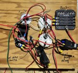
panel.jpg

Power from battery to fuse block. This wire has a 30A inline fuse.

1st circuit to batt terminal of ignition switch

2nd circuit to fuel pump on/off switch (Carter P4070)

3rd circuit to fuel pump relay

For the 3 gauges the light bulb wires (white) are combined and then to the batt terminal of the ignition switch.

The ground wires from the gauges (black) are combined and will be grounded to the run stand frame, along with the fuel pump relay and fuel pump on/off switch ground wires.

The ignition terminal of the ignition switch has connections to power the tach, the electric choke on the carb, and the ignition coil.

There is nothing on the accessory terminal of the ignition switch

The start terminal of the ignition switch has a connection to the starter relay.

I have the gear reduction starter from WH and a starer relay/solenoid from summit. The starter relay does not have any markings for the poles, are these directional?
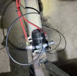

relay.jpg
The left pole has a wire to the starter and I need to connect a wire to this pole directly from the battery as well (I think..?).

The furthest right pole has a wire that connects to the starter as well (this is the wire that came with the starter).

I think the pole 2nd from the left that has nothing on it in this image is where I connect the wire from the start terminal of the ignition switch (?)

I think the pole 2nd from the right that has a black wire on it right now either connects to the positive terminal of my ignition coil, or I just leave that pole empty (?).

I’m using a pertronix billet distributor with an igniter 2 module, and an igniter 2 coil.


A couple other questions:

When is the batt terminal of the ignition switch excited? Will the gauge bulbs be on as soon as the battery is connected or will the key in the ignition switch need to be popped to the right?

If you were going to add wiring to this system for a 4g alternator how would you do that? or will it be able to run for the 20-30min break in period with just a charged battery?


I would appreciate some help here so I can get thing fired up!
Thank you
 

DirtDonk

Contributor
Bronco Guru
Joined
Nov 3, 2003
Messages
47,916
Wow, lots of stuff going on here!
But first, before I forget... You will need to bolt the starter relay to the stand instead of wire-tying it. It needs to ground through it's mounting bracket to function properly.

Also, have a timing light connected to the engine before you start cranking the starter. And will you have helping hands (and eyes) with you for the initial startup?
Reason I ask is that there is a lot going on during a first startup, even for long experienced builders. Someone who's done this a couple of times before can do it themselves, but even they can benefit from two or three pairs of eyes watching for leaks and checking the timing right away. You don't want the timing too far off (especially retarded) when you're revving it up to break in the cam.
And this is a flat-tappet cam we're talking about. Correct? A roller does not need an exotic break-in period like a flat tappet does, so wanted to check.
Does not hurt to run it for a few minutes at high rpm even for a roller, but it's not as critical.

If flat-tappet, are you using break-in oil and/or break-in additive to the oil? Along with a full slathering of the moly lube for the cam lobes presumably.
I'm looking for some help with wiring up my run stand. Never crimped a wire in my life before this and I'm trying to avoid a garage fire. What I've got here is pieced together from various youtube examples.

View attachment 911532
For the switches:
1. Is the center terminal of the ignition switch for BAT power? What is the unused terminal in the upper left?
2. Why are there three wires to the fuel pump switch? What do each of them do?
Power from battery to fuse block. This wire has a 30A inline fuse.
So far, so good!;)
1st circuit to batt terminal of ignition switch
Are you counting from the bottom to the top in the picture of the fuse panel?
Are the four terminals on the switch clearly marked, or did they supply a good diagram with the switch? If so, can you post it up just in case?

Just ran into the "thousand word limit" on my post. So more to come shortly...

Paul
 

DirtDonk

Contributor
Bronco Guru
Joined
Nov 3, 2003
Messages
47,916
#2

2nd circuit to fuel pump on/off switch (Carter P4070)
What's the Black wire for? Has a ring-terminal already crimped at the other end it looks like.
3rd circuit to fuel pump relay
Which terminal? Is it #30? Just checking...
For the 3 gauges the light bulb wires (white) are combined and then to the batt terminal of the ignition switch.
You can put the White wires either on BAT or on SWITCHED power. Personally I'd run them off of switched, so you don't have to disconnect the battery just to turn them off.
The ground wires from the gauges (black) are combined and will be grounded to the run stand frame, along with the fuel pump relay
The gauge grounds are for the lights only I would think. You can switch the relay's ground (#85) OR switched positive (#86) if you prefer. Grounding the relay and switching the positive is perfectly fine.
...and fuel pump on/off switch ground wires.
This is what I was questioning above. Why does a switch have a ground wire? Be careful here, as it might lead to a dead short and melt something. The only smoke you want to see is going to be coming out of the exhaust!
A switch for a pump should be just a straight through on/off (or open/closed) affair. No third wire.
Does your switch have only two, or does it have three positions?
The ignition terminal of the ignition switch has connections to power the tach, the electric choke on the carb, and the ignition coil.
Should be fine.
There is nothing on the accessory terminal of the ignition switch
ACC positions are usually hot in both ON/RUN and ACC. So if you run out of room on a crowded IGN terminal, you can swap some over to the ACC terminal.
For example, if you ever want to read the gauges without powering up the ignition coil (possibly overheating it if you leave it on too long without the engine running) you could power the gauges from the ACC terminal and not worry about leaving other things hot.
Just a thought...
The start terminal of the ignition switch has a connection to the starter relay.
This would be to the "S" terminal, usually located on the left side as it's oriented in your picture.
 

DirtDonk

Contributor
Bronco Guru
Joined
Nov 3, 2003
Messages
47,916
Third and last (hopefully!):

I have the gear reduction starter from WH and a starer relay/solenoid from summit. The starter relay does not have any markings for the poles, are these directional?
The big terminals are not polarity sensitive. A relay is just a switch, so it's either open or closed, and lets power pass through it in either direction. So no, the relay does not care whether the battery is on the left of the right.
The left pole has a wire to the starter and I need to connect a wire to this pole directly from the battery as well (I think..?).
Not necessarily.
You do not want two small wires to the starter. You need a truly battery cable sized wire (two of them ultimately) on one terminal.
So let's take the left side for the battery at the moment. There should be your main positive battery cable, then an equally big starter cable down to the main big terminal on the starter solenoid attached to the starter motor.
The right side terminal gets the regular wire down to the smaller terminal on the starter solenoid. Are they marked? I have not looked at one in awhile, but even if not, follow the instructions included with the starter. They should tell you all you need to know.

Connected this way, the starter is always hot with battery cables (but not active) and only cranks once the starter relay sends power down the smaller wire to the solenoid.
The larger of the two wires in your picture looks like the supplied wire? It's probably 10ga and should be the one you use. You can likely get away with the smaller size of the other one if you want, but no reason to under size wires at this point.

And speaking of sizing wires... Are you planning to use dedicated wires/cables for the stand only? Or are you going to use the same battery and starter cables for both the stand and the vehicle?
If dedicated/bespoke cables, you can use 6ga battery and starter cables. But for the truck I'd use 2ga at least. Just that bit of overkill that gives you some extra life down the road.
Keep them all as short as possible of course, while still being able to route them cleanly and keep out of the way of the spinny bits! Zip tie as needed for cleanliness and safety.
The furthest right pole has a wire that connects to the starter as well (this is the wire that came with the starter).
I should have re-read this first. So the right side wire came with the starter and is connected to the smaller terminal as per instructions?
I think the pole 2nd from the left that has nothing on it in this image is where I connect the wire from the start terminal of the ignition switch (?)
Yes.
I think the pole 2nd from the right that has a black wire on it right now either connects to the positive terminal of my ignition coil, or I just leave that pole empty (?).
Double yes.
For your use here, you probably will not need this wire on the "I" terminal for the ignition coil. It is there to help start during initial cold startups, or other difficult conditions. So it's a good thing, but it's not strictly needed here.
I’m using a pertronix billet distributor with an igniter 2 module, and an igniter 2 coil.
New stuff is just another reason for having the timing light connected before you crank.
Their stuff is generally good and reliable, but for this break-in you want to KNOW that it's sending sparks to the correct location.

Speaking of that... Do you know the firing order of your new cam? Is it the traditional 15426378, or 13726548?
When is the batt terminal of the ignition switch excited?
The BAT input to the switch is hot all the time of course. The BAT OUT or IGN maybe(?) is only hot when the key is turned to ON/RUN
Will the gauge bulbs be on as soon as the battery is connected or will the key in the ignition switch need to be popped to the right?
From the sound of it, they're going to be lit as soon as the battery is connected. I gave some thoughts on that above.
If you were going to add wiring to this system for a 4g alternator how would you do that?
Bolt the alternator to the engine. Make sure the mounting points are clean and free of paint and rust.
Just in case anyway, maybe add another dedicated ground wire from the alternator to the engine block.
Battery output cable (6ga is normal, but you can get away with 8ga if you have it.
If you don't have 8ga it's expensive enough to justify an inexpensive 6ga cable of the correct length to run from the BAT terminal on the alternator, over to the BAT side of the starter relay. Or directly to the battery if that's easier.
or will it be able to run for the 20-30min break in period with just a charged battery?
Yes, maybe. With a good modern and reasonably high capacity battery, you should get thirty minutes out of it.

Some more random thoughts:
1. Positive battery cable to starter relay left post. Along with starter cable to main lug on starter and possibly the alternator charge cable.
2. Negative battery cable to the engine block with 6ga or larger cable. Closer to the starter motor is better, but convenient and safe and out of the way of exhaust heat is even better.
3. Ground wire from battery to engine stand where it can be used as a common grounding point, or at least a way to ground the stand so that other things will work. This can be 10ga wire because it does not have to carry the load of the starter

Probably other stuff as well. So don't just fire it up on my say so. Wait for some others to add their twenty cents as well.
Better to be delayed and safe, than quick and let the smoke out!

Paul
 

DirtDonk

Contributor
Bronco Guru
Joined
Nov 3, 2003
Messages
47,916
Well crap. When I had to cut/copy and paste, it deleted the pics.
Normally I do that anyway, but this time I wanted to keep the pics in the answer to better see without having to scroll back and forth.

Oh well...

See if any of that makes sense.

Paul
 

73azbronco

Contributor
Bronco Guru
Joined
Nov 11, 2007
Messages
7,867
So my biggest lesson learned on engines, don't build or break them in until you are ready to drive the rig. Let it sit until it's ready to move.
 
OP
OP
C

CabinCruiser

Contributor
Newbie
Joined
Dec 5, 2021
Messages
56
Wow, lots of stuff going on here!
But first, before I forget... You will need to bolt the starter relay to the stand instead of wire-tying it. It needs to ground through it's mounting bracket to function properly.
Yup, thanks, zip tie is just for mock up.
Also, have a timing light connected to the engine before you start cranking the starter. And will you have helping hands (and eyes) with you for the initial startup?
Reason I ask is that there is a lot going on during a first startup, even for long experienced builders. Someone who's done this a couple of times before can do it themselves, but even they can benefit from two or three pairs of eyes watching for leaks and checking the timing right away. You don't want the timing too far off (especially retarded) when you're revving it up to break in the cam.
Good advice, thanks. Hopefully a parts house will loan me one of those, can't imagine I'd use it much.
And this is a flat-tappet cam we're talking about. Correct? A roller does not need an exotic break-in period like a flat tappet does, so wanted to check.
Does not hurt to run it for a few minutes at high rpm even for a roller, but it's not as critical.
Yup, flat-tappet
If flat-tappet, are you using break-in oil and/or break-in additive to the oil? Along with a full slathering of the moly lube for the cam lobes presumably.
Regular 5 gallon jug of 10w30 oil with an entire bottle of zinc additive added.
For the switches:
1. Is the center terminal of the ignition switch for BAT power? What is the unused terminal in the upper left?
Central terminal is START
Lower is BATTERY
Upper right is IGNITION
Upper left is ACCESSORY
2. Why are there three wires to the fuel pump switch? What do each of them do?
one of them is power in, one of them is ground, and one of them is load (to fuel pump relay)
Are you counting from the bottom to the top in the picture of the fuse panel?
Yup
 
OP
OP
C

CabinCruiser

Contributor
Newbie
Joined
Dec 5, 2021
Messages
56
What's the Black wire for? Has a ring-terminal already crimped at the other end it looks like.
Coming off of the fuel pump switch is a ground for the switch
Which terminal? Is it #30? Just checking...
the "load" connection on the fuel pump switch goes to the #86 terminal on the fuel pump relay

I have 4 connections on the fuel pump relay:
30 - main power from 3rd circuit of fuse block
85 - ground
86 - from fuel pump switch switch
87 - to fuel pump
87a - empty
You can put the White wires either on BAT or on SWITCHED power. Personally I'd run them off of switched, so you don't have to disconnect the battery just to turn them off.
Yeah, I'm thinking I'll just move the bulbs to the ACCESSORY terminal, because it's not being used and why not.....they are basically accessories.
The gauge grounds are for the lights only I would think. You can switch the relay's ground (#85) OR switched positive (#86) if you prefer. Grounding the relay and switching the positive is perfectly fine.
This I do not understand, see above my 4 fuel pump relay connections....please let me know if I need to change any of them
This is what I was questioning above. Why does a switch have a ground wire? Be careful here, as it might lead to a dead short and melt something. The only smoke you want to see is going to be coming out of the exhaust!
A switch for a pump should be just a straight through on/off (or open/closed) affair. No third wire.
Does your switch have only two, or does it have three positions?
I thought it only had 2 positions, but 3 connections....should I just delete that ground wire? I'll take a closer look at that switch when I get home...might just go back to grab one with two terminals....I want to be certain.
ACC positions are usually hot in both ON/RUN and ACC. So if you run out of room on a crowded IGN terminal, you can swap some over to the ACC terminal.
For example, if you ever want to read the gauges without powering up the ignition coil (possibly overheating it if you leave it on too long without the engine running) you could power the gauges from the ACC terminal and not worry about leaving other things hot.
Just a thought...
Yup, gonna do that. thanks
This would be to the "S" terminal, usually located on the left side as it's oriented in your picture.
Ok that's what I thought, good.
 
OP
OP
C

CabinCruiser

Contributor
Newbie
Joined
Dec 5, 2021
Messages
56
The big terminals are not polarity sensitive. A relay is just a switch, so it's either open or closed, and lets power pass through it in either direction. So no, the relay does not care whether the battery is on the left of the right.
Good clarification. Thank you.
Not necessarily.
You do not want two small wires to the starter. You need a truly battery cable sized wire (two of them ultimately) on one terminal.
So let's take the left side for the battery at the moment. There should be your main positive battery cable, then an equally big starter cable down to the main big terminal on the starter solenoid attached to the starter motor.
The right side terminal gets the regular wire down to the smaller terminal on the starter solenoid. Are they marked? I have not looked at one in awhile, but even if not, follow the instructions included with the starter. They should tell you all you need to know.

Connected this way, the starter is always hot with battery cables (but not active) and only cranks once the starter relay sends power down the smaller wire to the solenoid.
The larger of the two wires in your picture looks like the supplied wire? It's probably 10ga and should be the one you use. You can likely get away with the smaller size of the other one if you want, but no reason to under size wires at this point.

And speaking of sizing wires... Are you planning to use dedicated wires/cables for the stand only? Or are you going to use the same battery and starter cables for both the stand and the vehicle?
If dedicated/bespoke cables, you can use 6ga battery and starter cables. But for the truck I'd use 2ga at least. Just that bit of overkill that gives you some extra life down the road.
Keep them all as short as possible of course, while still being able to route them cleanly and keep out of the way of the spinny bits! Zip tie as needed for cleanliness and safety.

I should have re-read this first. So the right side wire came with the starter and is connected to the smaller terminal as per instructions?
Yes, the wire on the furthest right pole came with the starter, it goes to the small terminal on the starter
The wire on the furthest left pole is a wire I made which goes to the large terminal on the starter. It is 12ga. Sounds like you're saying I should replace it with a much larger wire (2ga), and also have a 2ga from the battery to that pole as well.
Double yes.
For your use here, you probably will not need this wire on the "I" terminal for the ignition coil. It is there to help start during initial cold startups, or other difficult conditions. So it's a good thing, but it's not strictly needed here.
If it isn't going to hurt anything I'll probably put it on there.
New stuff is just another reason for having the timing light connected before you crank.
Their stuff is generally good and reliable, but for this break-in you want to KNOW that it's sending sparks to the correct location.
Good advice
Speaking of that... Do you know the firing order of your new cam? Is it the traditional 15426378, or 13726548?
Off the top of my had I don't know, but I remember checking, double checking, and triple checking I had it right when I installed my distributor and cut/crimped my spark plug wires.
The BAT input to the switch is hot all the time of course. The BAT OUT or IGN maybe(?) is only hot when the key is turned to ON/RUN
From the sound of it, they're going to be lit as soon as the battery is connected. I gave some thoughts on that above.
In retrospect, that's pretty obvious, I'll just put them on the ACCESSORY terminal.
Yes, maybe. With a good modern and reasonably high capacity battery, you should get thirty minutes out of it.
Are you aware of any kind of charging device I could hook up to the battery, or another 12 V power source that would be better? If I had to charge the battery and restart the process 15 minutes into the break-in period how bad would that be for my CAM?
Some more random thoughts:
1. Positive battery cable to starter relay left post. Along with starter cable to main lug on starter and possibly the alternator charge cable.
2. Negative battery cable to the engine block with 6ga or larger cable. Closer to the starter motor is better, but convenient and safe and out of the way of exhaust heat is even better.
3. Ground wire from battery to engine stand where it can be used as a common grounding point, or at least a way to ground the stand so that other things will work. This can be 10ga wire because it does not have to carry the load of the starter

Paul
Thanks!
 
OP
OP
C

CabinCruiser

Contributor
Newbie
Joined
Dec 5, 2021
Messages
56
So my biggest lesson learned on engines, don't build or break them in until you are ready to drive the rig. Let it sit until it's ready to move.
My goal was to get a rolling chassis together before the snowy weather came to maximize the space in my 2-car garage so my wife can have room to park in there next to my project. In order to do that I had to build the engine....now that it's build I'd rather get it broken in so that if there's a huge problem I can deal with it now.
 

DirtDonk

Contributor
Bronco Guru
Joined
Nov 3, 2003
Messages
47,916
I’ll revisit this a little later. But basically no, you do not have to worry about stopping the process in the middle.
It is possibly better to keep it going in one stretch, but if you have to break it up into three 10 minute segments, or two 15 minute segments, or whatever, it doesn’t matter.
As long as you shut it down completely, and do not let it idle While running.
It either has to be running at 2000 or more RPM, or off.

This allows you to stop to fix leaks, or stop to fix a carburetor problem, or stop to fix an electrical problem, or oil pressure, or water temperature, or anything.

You can probably connect any normal battery charger of, for example 15 A or stronger, and keep the battery charged.
The running engine probably uses less than 10 A.
However, connecting your alternator and using that, at least let you know whether the alternator is working or not.
 
OP
OP
C

CabinCruiser

Contributor
Newbie
Joined
Dec 5, 2021
Messages
56
The fuel pump switch has an indicator light, I believe that's what the ground is for.
 

DirtDonk

Contributor
Bronco Guru
Joined
Nov 3, 2003
Messages
47,916
OK, good. Not a bad thing to have, and I completely ignored that possibility.
 
Top