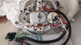
I'm in the middle of re-wiring my '69 Bronco using a Ron Francis kit. And as I got to the section for wiring the gauge cluster, I got to thinking about how we all know and gripe about how hard it is the remove or service the cluster (change bulbs, etc.) since you have to remove the speedo cable and then snake it part way out to disconnect and unplug the wiring and bulbs.
Since I'm wiring it 98% from scratch (reusing only a few factory connectors), I decided to ease future servicing by building a quick connect for all wires and circuits to the cluster. This will simplify cluster removal—disconnect the speedo cable and then the cluster connector. Done. No fishing around behind the dash.
There are 8 leads feeding the cluster:
Went to the local electronics store and picked up a set (male and female) of 9-pin Molex connectors and pins, and started laying it all out. Molex pins are designed to be crimped with a special double-crimp tool that I don't have, so I hand-crimped and then soldered all pins. I'm not totally done yet, but it is all going as planned and looks like it will work fine. In this picture I still have the 2 engine sender wires to finish up. Obviously, the other connector will look similar, and then feed the wires to their proper destinations.

Since I'm wiring it 98% from scratch (reusing only a few factory connectors), I decided to ease future servicing by building a quick connect for all wires and circuits to the cluster. This will simplify cluster removal—disconnect the speedo cable and then the cluster connector. Done. No fishing around behind the dash.
There are 8 leads feeding the cluster:
- 12v power to gauge voltage regulator
- Fuel sender (to main tank, or to tank switch, depending on whether you have both tanks)
- Oil sender
- Coolant sender
- Gauge lighting
- High beam indicator
- Left signal indicator
- Right signal indicator
Went to the local electronics store and picked up a set (male and female) of 9-pin Molex connectors and pins, and started laying it all out. Molex pins are designed to be crimped with a special double-crimp tool that I don't have, so I hand-crimped and then soldered all pins. I'm not totally done yet, but it is all going as planned and looks like it will work fine. In this picture I still have the 2 engine sender wires to finish up. Obviously, the other connector will look similar, and then feed the wires to their proper destinations.
Last edited:


