• Welcome to ClassicBroncos! - You are currently viewing the forums as a GUEST. To take advantage of all the site features, please take a moment to register. It's fast, simple and absolutely free. So please join our community today!
    If you have problems registering or can't log into your account, please contact Admin.

Resistor Wire Question

dprio34

Jr. Member
Joined
Feb 14, 2015
Messages
130
Loc.
Las Vegas, NV
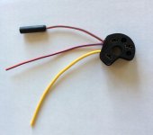
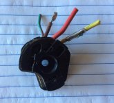
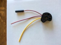
I am dropping in an aftermarket HEI Distributor (with coil mounted on top wheel well so I don't have to cut hood brace) and Re-wiring my Ignition Switch Pigtail at the same time due to it being mangled by PO.

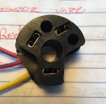
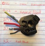
All guidance I have seen says, get rid of the resistor wire when running HEI. I guess this means wires, not wire? Both Pink #016 at Ignition Switch and Brown #214/262 at Starter Relay? Can anyone confirm?

Also, Can I wire a "home-run" from Green-red #904 at the Ignition Switch to the coil on the Wheel well, or will this cause loss of any systems, like brake lights, electric fuel pump, etc?

Thanks to all!!
 
Last edited:

gr8scott

Contributor
Bronco Guru
Joined
Jul 1, 2011
Messages
1,856
HEI requires 12 volts, so no resistor. Not sure the color of that wire.
The brown wire bypasses the resistor to momentarily send full 12 volts
(in key start position) to the coil when running points to assist in starting.
It is not needed for HEI.
 

Steve83

Bronco Guru
Joined
Jul 16, 2003
Messages
9,063
Loc.
Memphis, TN, USA, Earth, Milky Way
Referring to this diagram:


You'd either overlay or replace the original 16 Pk resistor (between the ig.sw. and C6) with a new wire (I'd use Pk ~16ga). That eliminates the resistance.

Then, depending on how your HEI is wired, you'd cut 16 Pk (which is NOT resistor wire) away from C1 and connect it to the HEI power input. And you might cut 262 Br away from C6, and either eliminate it, abandon it (properly insulated), or tie it in to the HEI (if necessary).

That's it - you shouldn't need any other wiring MODS (I have no idea about REPAIRS).
 

DirtDonk

Contributor
Bronco Guru
Joined
Nov 3, 2003
Messages
48,371
Or you could just leave the Brown wire for now. It's excess, but it's not hurting anything and is probably all under the hood.
If you're also re-wiring all the under-hood stuff at the same time, of course now's the tine to get rid of that Brown wire after all.

You will not cause any trouble by running a regular wire spliced into the Red w/green wire directly from the switch to the coil. It's expecting 12v and that's all this wire will do.

Steve, can you make a slight modification to your diagram if it's not too much trouble?
The ignition coil wire, at least on some years, is a separate wire with the resistor wire section actually inserted with a push connector into the circuit after the switch. So it's Red w/green at the switch, and Red w/green from the firewall to the coil. It's only Pink resistor wire from a few inches after the switch to the firewall.

Your diagram shows Pink all the way obviously, and that might be confusing to those just looking at the wire color and wondering where the Green w/red comes into play at the coil or switch.
Also, I see two resistor symbols. Is this normal and just to indicate that it's still a resistor wire along it's length? Or does more than one symbol on a circuit indicate anything else?
Seems like the factory diagrams only have one resistor symbol per circuit, so I was curious.
I've never seen any diagram show that there was a connector inline, but not sure how relevant that is, as they don't always show each and every connection.

We should try to find out if all years used the plug-n-play resistor wire, or if some years it was molded in.
The harness I have here that I was using for the photos of the fuse panel in our discussion the other day has the connector.
I just took some pics of it and will post them up as soon as they become available.%)
My phone only uploads new images when it wants to apparently.

Thanks

Paul
 
OP
OP
dprio34

dprio34

Jr. Member
Joined
Feb 14, 2015
Messages
130
Loc.
Las Vegas, NV
Paul, Steve, and Scott, Thank you for all the help. I think I will just run a new 16 ga Red/Green wire from the new Ignition Switch Socket to the coil and eliminate the Pink and Brown all together. Steve, thanks for the 1972 specific diagram.

Paul, the aftermaket Ignition Socket has a "large" female socket / push connector at the end of the Red/Green wire. Am I missing a male end? I am going to cut that out unless you tell me I should be doing something else. Thanks Again, Don.
 

Steve83

Bronco Guru
Joined
Jul 16, 2003
Messages
9,063
Loc.
Memphis, TN, USA, Earth, Milky Way
Steve, can you make a slight modification to your diagram if it's not too much trouble?
As its caption indicates, I'm prepared to make LOTS of changes to that diagram. At this point, it's just a cleaned-up & combined version of Seabiscuit's diagrams, with a few corrections that were obvious to me. I don't have a '72 & have never seen one's wiring, so whatever the consensus here is, I'll put it into that diagram.

But to get the changes you described correct, I need to know:
1) the gender of the connection where the ig.sw. Gn/R changes to Pk (a photo of the separated connection would do)
2) the location of the Br connection to the circuit (in Gn/R or in Pk; and which side of the firewall)
3) any connector numbers, circuit numbers, splice numbers, resistance wire value, and locations you're aware of.

Yes, the 2 resistor symbols were just to show that the whole wire is resistor; without a resistance value number on the symbol, it's almost meaningless. Every connector SHOULD be shown in an accurate wiring diagram.
 
OP
OP
dprio34

dprio34

Jr. Member
Joined
Feb 14, 2015
Messages
130
Loc.
Las Vegas, NV
Here are some pics.
At Starter Relay, 2 from top of Manifold, and old Ignition wiring socket with (4) wires, new Ignition wiring socket with (3) wires.
 

Attachments

  • IMG_8684.jpg
    IMG_8684.jpg
    120 KB · Views: 28
  • IMG_8691.jpg
    IMG_8691.jpg
    108.9 KB · Views: 33
  • IMG_8692.jpg
    IMG_8692.jpg
    111.3 KB · Views: 33
  • IMG_8695.jpg
    IMG_8695.jpg
    107.1 KB · Views: 32
  • IMG_8698.jpg
    IMG_8698.jpg
    64.1 KB · Views: 26
Last edited:
OP
OP
dprio34

dprio34

Jr. Member
Joined
Feb 14, 2015
Messages
130
Loc.
Las Vegas, NV
Well, I took the plunge and cut the old Ignition Socket/Harness. Ran a home run from the Red/Green on the new socket to the positive side of the Coil. Nice clean spark. However, somehow I took my electric fuel pump out of the equation. Engine is not getting fuel in "Start" or "Run".

I am not feeling very smart because I cannot for the life of me figure this out.

Carter Fuel pump is on a relay activated by the old Green/Red wire.
Spliced the old Green/Red into the new Red/Green with the new home run to the coil.

What did I do when I cut out the old Ignition Socket? Any assistance, most appreciated.
 
Last edited:
OP
OP
dprio34

dprio34

Jr. Member
Joined
Feb 14, 2015
Messages
130
Loc.
Las Vegas, NV
Yes, it is a female connector. It is the After Market Ignition repair socket from WH part #6306. I gather from what Paul was saying, some Early Bronco had an in-line connection for 904 and 016? My Green/Red and Pink are inside the old socket w/o connector. Had me scratching my head, for sure.
 
Last edited:
OP
OP
dprio34

dprio34

Jr. Member
Joined
Feb 14, 2015
Messages
130
Loc.
Las Vegas, NV
Here are the old and new side by side. Connector on the Red/Green is Female.
 

Attachments

  • IMG_8705.jpg
    IMG_8705.jpg
    108.4 KB · Views: 15
  • IMG_8697.jpg
    IMG_8697.jpg
    58.8 KB · Views: 10
Last edited:
OP
OP
dprio34

dprio34

Jr. Member
Joined
Feb 14, 2015
Messages
130
Loc.
Las Vegas, NV
Sorry, the socket on the Red/Green wire is Female. Below are some more pics. The Female end is rather large inside and I had nothing in my hardware to make a connection to it. So, I cut it off since I do not have a male connector under my dash at the ignition switch. Still haven't solved the problem with the electric fuel pump not getting power via the relay. I guess I will have to wire Pink 016 back into the equation, just not sure where. I am guessing at the relay with the trigger Green/Red. Any input, most appreciated.
 

Attachments

  • IMG_8707.jpg
    IMG_8707.jpg
    89.8 KB · Views: 11
  • IMG_8708.jpg
    IMG_8708.jpg
    105.9 KB · Views: 13
  • IMG_8709.JPG
    IMG_8709.JPG
    63.7 KB · Views: 10
  • IMG_8710.jpg
    IMG_8710.jpg
    70.5 KB · Views: 8
Last edited:

DirtDonk

Contributor
Bronco Guru
Joined
Nov 3, 2003
Messages
48,371
Here's the factory version. I need to trace that additional wire coming out of the female connector, but it's probably the Green w/red pigtail spliced into the Red w/green.
So for Steve, it's a female on the switch side, male on the harness side.

039s.jpg

dprio, you probably lost the fuel pump relay because those are two separate circuits. You need to re-connect the old Green w/red because that's what apparently was used for the fuel pump. It's originally for the under-hood external voltage regulator. Whether you still have the regulator or not, you may also have lost it's function as well.

You may only have had one wire coming off of the switch connector, but it split into two separate functioning circuits. One had the resistor wire and was for the ignition only. The other was for the voltage regulator and any other circuits that were hot in RUN only.

As said, you need to keep digging into that thing, but also post some pics just for our curiosity.

Thanks

Paul
 

DirtDonk

Contributor
Bronco Guru
Joined
Nov 3, 2003
Messages
48,371
Interesting... There's that Green w/yellow that you were talking about being in Seabiscuit's drawings Steve.

Paul
 

DirtDonk

Contributor
Bronco Guru
Joined
Nov 3, 2003
Messages
48,371
Here's a known-'73 Steve.
Has the resistor wire run straight into the main switch connector:
047s.jpg

And for reference in the other discussion, the fuse panel does NOT have the additional connections:
046s.jpg

Here is the front face of the panel:
044s.jpg

Paul
 

Steve83

Bronco Guru
Joined
Jul 16, 2003
Messages
9,063
Loc.
Memphis, TN, USA, Earth, Milky Way
...that additional wire coming out of the female connector, but it's probably the Green w/red...
It looks like R/Y to me.

So is the short wire from the ig.sw. to the green rubber R/Bu or R/Gn? And the pic doesn't show the other Gn/R coming off the ig.sw. - is that where the R/Bu or R/Gn wire comes from?
There's that Green w/yellow...
Where are you talking about? What I was talking about isn't actually a Gn/Y. Seabiscuit just misinterpreted "GY" on his diagram and colored it Gn/Y instead of Gy. dprio's pic shows it to be Gy, so I corrected it on my '72 diagram (which I haven't uploaded yet).
Here's a known-'73...
Good info. Thanks. I'll add it to the '73-74 diagram.

******
That fuse block says hazard & stop are on the same fuse, but the diagrams I have for '73-74 show stop power coming off the headlight switch's internal breaker. Can you trace the R wire from the stop switch in that harness and find where it actually comes from?
 
Last edited:
Top