


Tech article by Larry Crumpler (MarsChariot), Phil Lindenmuth (Viperwolf1), Casey Nicholas (needabronco), Jake Norton (recoiljunky), Todd Zuercher (toddz69) and Randy Silbaugh (ransil)
This ClassicBroncos.com tech article covers the steps necessary to install a serpentine belt drive system on your Bronco (Fig. 1) using parts from a ’96-’01 model Ford Explorer or Mercury Mountainer with 5.0 engine. Although the discussion below appears long and involved, the conversion is actually fairly simple. The length of the tech discussion is simply to make sure we to cover each of the main components, the variations in how to handle them according to what engine you are using (302, 5.0, 351), and the usual array of questions that come up about each step regarding parts and fitment. Many Bronco owners can just go to the parts lists, and skim through the sections on power steering hoses and fan shrouds. Other may want to read the whole thing just to make sure they are not “going in blind” and missing something, especially since there are a few points that may not be obvious when you start.
[caption id="attachment_1388" align="aligncenter" width="500" caption="Figure 1. Example of the Explorer 5.0 serpentine belt system installed in an early Bronco. Note that all the accessories are mounted high, instead of being buried in the dark reaches of the engine bay. This particular example is on a 5.0 Ford Racing crate motor. (The A/C compressor bolts are close to the inner fender, so keep that in mind; you may want to have the compressor in place before bolting the bracket up. Access holes in the inner fender, filled with rubber plugs would be nice so you can remove it later if need be.)"]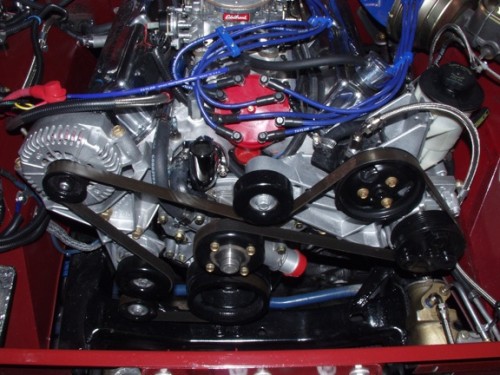 [/caption]
Finally, all six of the authors have contributed solutions for a wide range of the installation questions that come up for stock 302, 5.0, and 351, using various radiators and other commonly differing components used in early Broncos. So, if there are any specific questions not addressed in the following, it is probably best to simply post the question on the ClassicBroncos.com Bronco Tech forum under the heading “Explorer Serp Tech Help”. Since there are many others who have done this conversion, you will get answers from the person(s) who can bring the most experience to bear on your question.
A Few FAQS:
• Does this article tell me how to install an Explorer Serpentine drive on an older 302? Yes
• Does this article tell me how to install an Explorer Serpentine drive on a 351? Yes
• Does this article tell me how to delete the A/C Compressor? Yes
• Does this article tell me how to use another crankshaft pulley instead of the Explorer one? Yes
• Is the Explorer power steering pump strong enough for BIG tires? Yes
• Are there lots of clearance problems? There are several, but the fixes are easy and clean.
Why install a Serpentine Set-up?
The factory V-belt system works fine and can provide adequate service, but the serpentine systems used in most later model engines have several advantages for Broncos:
(1) The factory serpentine systems are on late model vehicles, so the accessories designed for the serpentine systems have benefited from the latest improvements derived from a couple of more decades of experience with design and maintenance of belt-powered accessories.
(2) Late model parts, including the belt-driven accessories, are more widely available and in most cases are designed for heavier loads. The 4G alternator (basically an upgraded 3G designed to fit the Explorer brackets, according to our one and only “RRRAAAYYY”) is a good example. The typical serpentine alternator puts out over four times more amps than the original alternators. The 4G is so potent that it has even been used to make a home-built small welder for sheet metal.
(3) Most serpentine systems mount the critical accessories like alternators and power steering pump high up on the front of the engine, out of the way of road spray, salt, water, and heat and are easier to access and maintain.
(4) No one can argue with the fact that since serpentine systems use a tensioner to maintain the belt tension, and use only one belt for the entire front of the engine, the ability to easily install the belt, in most cases in a matter of minutes, and to maintain the correct tension, is made a lot easier. And you do not have to jack on the side of any accessory to tighten a belt, or guess at the right tension (which most of us probably set too tight anyway).
(5) The Explorer bracketry is stiffer than conventional V-belt brackets and thus the accessories are held in better alignment to each other and to the engine. The more rigid structures also reduce noise, vibration, and harshness in the power train.
(6) Finally, to put the durability and functional superiority in perspective, the Explorer engine cooling, A/C system, and electrical accessories were designed to provide dependable, low maintenance and carefree service to one of the most demanding service situations, the SUV-driving soccer mom! Some automotive engineers will tell you that is not just hyperbole to say that compared to the demands imposed by that situation, off-roading is benign.
Why the Explorer Serpentine Set-up in particular?
The Explorer 5.0 serpentine belt system is one of two most common ways to add a factory serpentine set-up to the small block engines used in early Broncos. The other popular choice is the Mustang 5.0 serpentine belt system. The Explorer has a few advantages. First, it uses a mechanical clutch fan that is capable of impressive cubic-feet-per-minute (“CFM”) air movement through the radiator. Many people claim that it is the best mechanical fan option out there for early Broncos. The Mustang 5.0 serpentine arrangement, on the other hand, puts the fan closer to the radiator than the stock Bronco configuration. During off-roading when the engine and frame flex relative to the body, the fan can (and will!) come into contact with the radiator if the clearance between the two is too small. Because the Explorer timing cover is shorter (it does not have a fuel pump adding to the depth of the cover) the fan is much farther away from the radiator than the typical Mustang 5.0 serp set-up, so fan clearance is not a problem. In fact, it is almost too far away (see below). But it turns out that it is easier to fix that than to fix a fan that is too close.
The Explorer power steering pump is no slouch either. In fact it is very similar (not identical in output) to the power steering pump found on Superduty trucks. So if you are wondering if it can handle those big meats on your rims, be assured that it is a good pump. The 4G alternator on the Explorer set-up is the cream of the crop, and puts out a lot more amps than the original alternators that came on Broncos.
And the original Explorer A/C compressor will work with most of the 134a-based A/C systems such as Vintage Air or BC Bronco’s A/C kit. So if you have A/C on your list, it will work just fine. The Explorer compressor is a Visteon model FS10. If you need an electrical connector for the A/C compressor you can find it at NAPA, Echlin part #ACC100. If you don’t want the A/C compressor, then you can easily delete it, as will be shown below.
In more subjective terms, the Explorer serpentine system and accessories are more truck-like in their size and casting strength. Finally, the Explorer serp set-up beats aftermarket serpentine systems simply because it was designed specifically by the manufacturer for the small block Ford, is made of durable castings, and parts, belts, and accessories are readily available over the local parts counters. And to many of us, the brackets just look better. Additionally, most aftermarket serpentine systems still require manual tensioning of the belts using a threaded turnbuckle or strut arrangement; easier than V-belts, but not as nice as the factory spring-loaded tensioning system which loads the belts precisely to factory specifications.
What are the disadvantages of the Explorer serpentine set-up?
Depending on your point of view, and some things that you may want to do that can’t be done easily with the Explorer serp brackets, the Explorer serpentine set-up may be considered as having some disadvantages. In terms of availability, it has been less common than the Mustang 5.0 serpentine system, so it is may be less available in salvage yards, which could be a problem with finding one. (Some of us would say “non-existent”, but that can be fixed; see below.) However, in recent years, as the 5.0 Explorers have started to appear in the salvage yards, the availability has increased greatly. This disadvantage of limited availability may be changing to an advantage as late model Explorers are becoming more common in salvage yards these days than ’87-’93 Mustangs. Explorers were the number one trade-in in the Cash-for-Clunkers program, which may correlate with salvage yard appearances somewhat in the next few years.
The lower idler pulley is close to the cross member on the frame, which will need to be looked at carefully. There are a couple of things outlined below that can be done to make sure this is not a problem. And some people feel that since the power steering hoses will need to be fabricated, then that can be another dollar sink. But it is really not expensive and has the additional advantage that you can make your own hoses easily, as will be shown below, so others of us think that is a big advantage.
5.0 versus 302/351 differences. One issue that comes up early in the conversion is the fact that the lower crankshaft pulley on the Explorer 5.0 is integrated with the crank balancer. Although the 302/5.0 small block engines are the same displacement, the thing that is different (other than firing order and a few other details) is the balance. Pre-1981 302s and all 351Ws use a 28 oz. external balance, and 1981-up 5.0s use a 50 oz external balance; this means they use different harmonic balancers and different flywheels. Late model engines can simply bolt on the Explorer balancer because the Explorer engine is a “5.0”. But what do you do if you have an earlier small block, a “302” or a 351? To adapt the Explorer crank pulley/balancer to a 28 oz. engine you can do one of four things: (1) have a machine shop rebalance your existing Explorer balancer, (2) you can go to www.damperdudes.net, which does an excellent job, and for $115 total will rebuild, rebalance, and ship your balancer in about a weeks time, (3) if you are doing a build on an engine you could have your crankshaft and flywheel re-balanced to 50 oz external balance, or (4) call Randy at www.drivenautoparts.com who has an adapter pulley to bolt on to your existing 28 oz. 3 bolt balancer. His pulley is right at $75 (at this writing) and is a very nice piece.
Since the Explorer timing cover does not have a fuel pump boss, you will need to convert to an electric pump. This may not be such a bad thing, as good mechanical pumps are getting hard to find, and many are cheap, quality control is low, and may or may not last long either. So going to an electric can be a blessing. They are pretty reliable and nearly bomb-proof these days. Finally, the Explorer has an integral mechanical clutch fan, so it disengages at highway speeds, but runs during slow speed crawling, pulling more air than an electric, and it is excellent of course. The difficulty is that when swapped into an early Bronco the fan may not be covered enough by the stock radiator fan shroud. As a general rule fans need to be slightly inside the shroud or they will pull air from the sides instead of pulling it through the radiator. The fan should be at least a third of the way inside the shroud. Half way in is better. To accommodate this with a stock shroud, some sort of shroud extension must be installed. This is no problem, as will be shown, but it is just another step necessary in the proper installation. Some who have done the conversion do not appear to require it, others do. So it is something to consider, especially if your cooling system tends to be marginal on hot days.
Parts Needed for the Conversion
As far as the brackets go, it is easiest if you find the complete serpentine brackets and pulleys on a 5.0 Explorer/ Mercury Mountaineer (1996-2001) in a salvage yard and remove it yourself. Getting the bolts and making sure you have all the miscellaneous pieces like the clutch fan keeps the project simpler. If you are not junk yard savvy, don’t have the time to go hunting, or you live in a part of the world where, judging from their availability (or lack thereof!) 5.0 Explorers apparently did not exist (one state may have tons of them and the next state over there are none) you can get on line and search the nation’s used car parts businesses for a set-up. There are several used parts search systems on the internet wherein you specify what you are looking for and, if someone has that in their yard, they send you a note. That’s what one of us did and found one in Cleveland. The cost will probably be higher, with prices ranging from $100-$600. But if the search is taking too long, frankly the higher price is worth it just to be done and finished. (You will not find an aftermarket serpentine drive any cheaper, either, and they have the above noted issues anyway.) Life is too short to spend it looking for the perfect deal. Also, if any one part is not available during your search, with the exception of some obvious parts, you can just go to the parts store and buy the darn things.
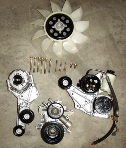 Collection of all the main factory parts that you will need in order to convert your Bronco to the Explorer serpentine belt drive system. Note: some years of Explorers came equipped with a steel fan, which is also suitable for this conversion.
Below are the parts you will need. (And Figure 2 is a picture of the main components that you will want to acquire.)
• Explorer short timing cover and water pump with pulley
• Explorer crank pulley and harmonic balancer (optional, see below)
• Passenger side alternator bracket with tensioner and lower idler pulley
• Driver side power steering and A/C compressor bracket with upper idler pulley, power steering pump, and power steering reservoir
• Explorer clutch and fan
• Make sure you get ALL of the mounting bolts as they are nearly impossible to find aftermarket (if you can’t, see the sizes listed below and see what you can come up with)
Then there are a few items that will be needed to complete the conversion
• Serpentine belt for model year of serp brackets and accessories (there is some variation in pulley designs)
• Felpro TCS 45449 Gasket kit including water pump, timing cover, oil pan end seal and front crankshaft seal (about $12)
• You will need a new high pressure hose for the power steering, because the stock Explorer hoses will not work for our application, but the solution for those will be listed later
• (optional) Some thick aluminum sheet metal (best sourced from a local metal supplier, not the hardware store stuff) and miscellaneous small 8-32 x ¾ screws/nuts/washers to make a fan shroud extension
Installation Overview
The Explorer serpentine system is a mostly bolt-on operation. But like most custom installations there are a few things that need to be considered (in other words, fabricated) if you are to do the job right or avoid any unnecessary surprises. The installation can be broken down into nine main components and steps that you will need to deal with, most of which are fairly trivial:
(1) Timing Cover/Crank Pulley: Installing the Explorer short timing cover, water pump, and crankshaft pulley-harmonic balancer
(2) Accessory Brackets: Bolting on the two accessory brackets and the accessories (alternator, power steering pump, and (optional) A/C compressor)
(3) Alternator wiring: Converting the wiring to the Explorer 4G alternator
(4) Power Steering hoses: Plumbing the power steering pump to your power steering gear
(5) Fan/Radiator shroud: Attaching the Explorer clutch fan and accommodating the increased distance between the fan and the radiator with fan shroud modifications
(6) Radiator Hoses: Depending on whether you are using a stock radiator or a “reversed” inlet/outlet 5.0 type radiator, there are a few options for radiator hoses
(7) Miscellaneous Options, like the coil mounting option.
(8) Belts: Depending on whether you keep the A/C compressor or remove it, or whether you are doing the conversion on a 351, there are some alternatives to the stock Explorer 5.0 belt.
(9) Electric fuel pump: Installing an electric fuel pump (the Explorer short timing cover does not have a mechanical fuel pump boss)
(1) Explorer timing cover and pulley
[caption id="attachment_1390" align="aligncenter" width="400" caption="Figure 3a. Typical 5.0 Explorer timing cover and integral balancer-crank pulley. You will want to substitute the gold piece in this picture (crank position sensor, which you will not need) with a simple timing pointer (see Figure 4)."] [/caption]
Cover. The timing cover and the pulley (Fig. 3A) are unique to the Explorer 5.0. The cover does not have a fuel pump boss and the crank pulley is integral to the harmonic balancer. So you will need to source these to get started. (See below for some options.) These come up on EBay from time to time (at least for a while when Ford Racing was offering a new 5.0 that had the Explorer timing cover and Mustang guys would buy them and sell the timing cover and pulley to go with the Mustang style serp instead). Or if you are lucky enough to have a 5.0 out of an Explorer you are good to go.
Installation is pretty much like any Ford small block timing cover, so follow all the rules on that, especially getting the crankshaft seal up to spec if its old. If you have a fuel pump eccentric for a mechanical fuel pump it will need to be removed and the cam pin may need to be cut or ground so the washer sits flush on the cam gear. The cam pin protrudes through the eccentric to lock it to the gear. Late model engines without a mechanical fuel pump may have an L-shaped oil slinger installed under the cam bolt. This would also need to be removed. Also note that some timing gears are wider than stock and may require other modifications to fit under the Explorer cover. For example the cam bolt head in Figure 3A needed to be milled 0.090” to provide adequate clearance. Your best course of action is to check your cam bolt to timing cover clearance prior to final installation of the timing cover.
Also the Explorer water pump is pretty specific and is necessary in order to mount the fan, so make sure you have that. It’s recommended that you purchase a new water pump at the time of installation and not re-use a used pump with an unknown (probably high) number of miles on it. The water pump is especially adapted to the Explorer fan with special threads on the end of the pump shaft and pulley attachment points.
Hopefully you will have gotten a complete cover with the water pump and the attaching bolts. If not, the water pump bolts and sizes are identified in Figure 4A. Water pump pulley bolts are 5/16” - 28 thread, 1/2” long.
[caption id="attachment_1392" align="aligncenter" width="500" caption="Figure 4A. Water pump mounting bolts. Also in this picture you can see the Explorer timing sensor (which you will remove and replace with a timing pointer) at the 10 o’clock position next to the crankshaft pulley"]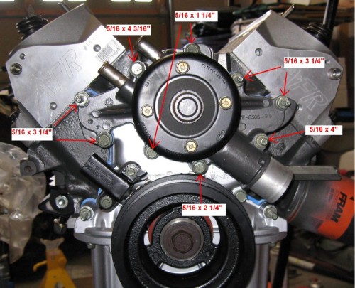 [/caption]
Crank Pulley . Torque the harmonic balancer/pulley crank shaft bolt to 110-130 ft-lbs. If your engine is balanced for 50 oz., then you can simply swap the Explorer balancer. The balancer is for the 5.0 flywheel so if you are using a 5.0, a 5.0 balanced flywheel will be necessary, too. The right size to get would be from a 1987 F-150 5.0, and runs about 80 bucks at NAPA; Mustang flywheels are too small and have different starter ring gear teeth counts). The Explorer balancer may also be purchased through NAPA if you were unable to get one at the time you acquired the other components of the serpentine set-up.
But there is another option, especially if you are starting with a 302 or 351. The original Explorer balancer is for 50 oz. external balance crankshafts. If your engine is the older Bronco 302 (i.e., pre-1981) or a 351 (all 351Ws are 28 oz. balance), then you should either have the Explorer balancer rebalanced or order the aforementioned adapter pulley. Incorrectly matching 50 oz. and 28 oz. parts can and will cause all sorts of vibration and drive ability problems.
Timing Pointer. The existing timing pointer mounting located at the 11 o’clock position location (actually on the Explorer it is an variable reluctance electronic trigger arrangement, not a timing “pointer”; see picture above of the timing cover) can be used as a timing pointer mounting point. (Note: This may be true for some years but some find that the pulse trigger also has a pointer and it matches the timing marks on the balancer. If so, it can be used as is with the Explorer balancer.) The Top Dead Center (TDC) mark is stamped on the side of the damper in very faint marks like a standard Bronco damper. If you are making a timing pointer to replace the electronic trigger, then the big groove in the pulley is not TDC and should be ignored. To make use of the TDC marking, simply make up a sheet metal pointer to replace it and just mount it to the original holes where the sensor was mounted (Fig. 4B). You can also use a stock 92 Ford EFI timing pointer.
[caption id="attachment_1393" align="aligncenter" width="500" caption="Figure 4B. Here is the timing pointer location, and an example of one that you can make up. Start out with a piece of cardboard and fab it to fit before cutting metal. A piece of aluminum or sheet metal will do fine. The timing marks are not easy to find. Worse still, there is a big groove in the damper that looks like a timing mark but is not. So look carefully."] [/caption]
Early Bronco 302s have the timing pointer at the 2 o’clock position. If you’re retrofitting the serp system to an early 302 with the Driven Auto pulley you will have to re-index your existing balancer marks to use a pointer at the 11 o’clock position. Mr Gasket timing tape, PN 1594, can be used for this. If your balancer is in questionable condition you can replace it with one indexed for the 11 o’clock timing position. Just remember to match the balance of the original balancer.
You can be very precise and make sure that your pointer agrees with TDC as determined via the usual compression stroke method. Or you can go high-zoot and use a degree wheel. Here’s an additional check: The stock Explorer damper has what looks like gear teeth all around the engine-side of the crank pulley. There are 35 of these teeth evenly spaced every 10 degrees around the pulley, and a gap where the 36th tooth would be. The gap is located at 60 degrees before top dead center. Top Dead Center then is located at the sixth tooth from the gap. This should correspond with the location of the actual stamped TDC marks. The pulley is black, and the letters are tiny, so I did not even know they were there. Frankly I could not find the TDC marks until I did this exercise with the teeth on the pulley.
(2) Installing the Ford Brackets
The brackets are thick aluminum castings onto which are mounted the pulleys and the accessories (alternator, power steering pump, A/C compressor, and belt tensioner). These brackets are each held onto the front of the left and right cylinder heads with three long bolts. Almost every (though apparently not all) Ford small block (including aluminum head crate motors) out there have these holes already there, tapped, and ready to accept these bolts and in the sizes that were on the Explorer heads. (There are a few exceptions in which the heads have threads that are smaller, but this is rare.) It is best if you can get the bolts with the serpentine set-up. But if you can’t, the proper sizes are shown in Figure 5A; although these are almost impossible to find in the right lengths and sizes. If you find a bracket set-up without them, the price should be a lot lower (by the cost of the tank of gas you will use trying to find the bolts!) to compensate for this. The alternator bracket may also have a lower bolt that goes to the block just under the head (Fig 5B). This bolt will not line up when used on a 351W. It is not absolutely necessary, but it does provide some more stiffness.
[caption id="attachment_1394" align="aligncenter" width="333" caption="Figure 5A. Location of bolts attaching the left and right serpentine brackets to the front of small block heads. The bolt sizes are shown in case you need to go buy those separately. If you are lucky, you will have gotten those with the brackets. On some brackets there is also another stiffener bolt down behind the tensioner."] [/caption]
[caption id="attachment_1418" align="aligncenter" width="499" caption="Figure 5B. This bolt is not used on the 351W. The power steering/A/C compressor bracket is shown on the right (in this view rotated 90 degrees counterclockwise from its mounted position). These represent all the idler pulleys and can be rebuilt with new bearings if your serpentine setup came from a high-mileage engine."]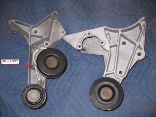 [/caption]
There are no clearance issues with the accessories other than those discussed below despite the width of the serpentine drive arrangement. The A/C compressor bolts are close to the inner fender on the driver’s side, so keep that in mind; you may want to have the compressor in place before bolting the bracket up. Access holes in the inner fender, filled with rubber plugs would be nice so you can remove it later if need be.
Lower Idler Pulley Clearance. The lower pulley on the passenger side of the engine just below the tensioner pulley is in most cases very close to the Bronco front frame cross-member (Fig. 5C). But there is usually at least ½ inch of clearance or more. However, if there is less than ½ inch clearance, the necessary clearance might be attained by a spacer fabricated to slip between the motor mount and the engine block. Or you might get away with “extreme” type motor mounts, which give you on the order of another ¼ inch of engine lift. Or you may (like most of us) have no problem at all. Some people have even notched the frame and “boxed” the notch for strength, but that is an extreme method to be used only if you cannot go higher with the engine. And if you consider it, you need to talk to a professional race car builder or someone with equivalent experience. Frames, even cross members, are not to be messed with lightly.
[caption id="attachment_1419" align="aligncenter" width="500" caption=" Figure 5C. The lower passenger side belt idler pulley can be very close to the frame. There should be a minimum of ! inch clearance. If it is less, the easiest option is to raise the enigine with shims between the motor mount and block."]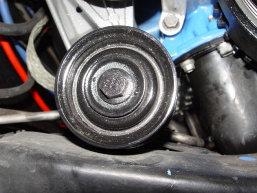 [/caption]
TFI Module Clearance. The Explorer 5.0 used a distributor-less ignition and was not designed with a standard distributor in mind, so using the Explorer brackets with the typical TFI distributor on an EFI conversion are not designed to allow the range in rotation of the distributor that is needed while timing an engine. The upper serpentine idler pulley support (Fig. 5D) can get in the way of the TFI module that sticks out tangent to the distributor. If the distributor is clocked carefully on installation, there is a “sweet spot” where it will have the necessary clearance throughout any likely arc during timing adjustment. But if this still does not work, it is possible to do some slight clearancing of the bracket just behind the upper idler pulley to get some additional motion. The metal is soft, so this can be done with some careful grinding and shaping to make it look pretty.
[caption id="attachment_1420" align="aligncenter" width="500" caption="Figure 5D. The TFI module can interfer with the serpentine bracket. Soutions include clearancing the bracket slightly or installing the distributor slightly counterclockwise (maybe about 1 tooth over)."]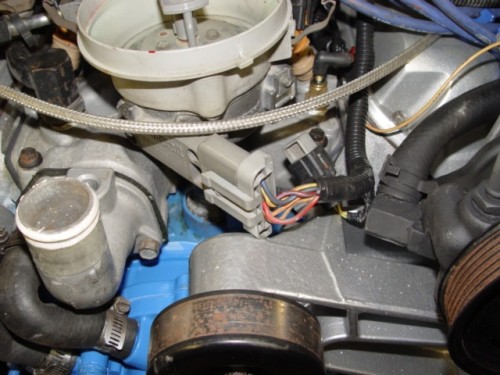 [/caption]
Oil Pressure Sensor Clearance. One more thing that should be checked is the oil pressure sensor. Commonly this will contact the lower part of the driver side bracket near A/C Compressor attachment point. The simple fix is to clock the oil pressure sensor extension tube clockwise (toward the rear of the engine) a few degrees instead of the usual position pointing straight up. This should provide the necessary clearance (Fig. 5E). You may need to back the extension completely out first if it is already tight and clean the threads carefully (this is an oil passageway). Then when you go back in, tighten it enough for a seal using some thread sealer while clocking it to just the right angle.
[caption id="attachment_1421" align="aligncenter" width="500" caption="Figure 5E. View with the A/C compressor not mounted in order to show the oil pressure sensorto- bracket clearance. In most cases, clocking the oil pressure sensor extension housing provides clearance."] [/caption]
(3) Alternator
The 4G alternator housing is specifically designed for the Explorer serpentine brackets and attaches with three mounting bolts that are metric, M10 x 75mm with 1.5mm pitch. One option to consider is using one of them to attach your negative battery cable when installing the alternator. This is especially true if you have painted or power coated the brackets. Or you could use the lower stiffener bolt on the passenger side serpentine bracket. In either case, just be sure to also run a good heavy-duty ground strap from the engine to the body.
As far as the alternator itself, the wiring is fairly straight forward. The old external voltage regulator and old alternator harness will need to be removed from the electrical system. The green-red wire that went to the old regulator “S” terminal will be used to provide a start signal to the new 4G alternator “I” terminal. Below (Fig. 6A) is a diagram from Ryan’s EFI site that pretty well says it all. Ignore the charge indicator lamp and the 510 ohm resistor in this diagram; it’s not used on an early Bronco. The next diagram (Fig. 6B) is more of a schematic from the standard Bronco wiring diagram that has been altered to show how this fits into the real-world situation. (Note: We show the battery cable going to the starter directly, but this applies only if you are using a mini-starter. Otherwise it should go through the starter solenoid like it was from the factory.) So the green-red power goes to terminal “I” and a yellow wire goes from “A” to the output terminal, and the output goes directly via a heavy battery cable to the battery positive. That’s it.
[caption id="attachment_1422" align="aligncenter" width="499" caption="Figure 6A. Diagram from Ryan’s web site showing the wiring for a 4G alternator."]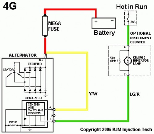 [/caption]
[caption id="attachment_1423" align="aligncenter" width="500" caption="Figure 6B. Diagram for normal folks modified from the factory drawing that we are all familiar with. The voltage regulator and ammeter are removed from the circuit."]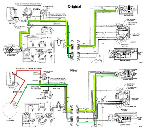 [/caption]
Because the ammeter on the stock gauge cluster is no longer functional once you convert to the 4G alternator (the stock ammeter wiring cannot handle the current output from the 4G alternator), the best thing to do is to try one of the voltmeter conversions that several people have found. These actually fit in place of the ammeter gauge. Or you can just ignore the ammeter gauge for the time being and put a voltmeter conversion on your to-do list for the future.
(4) Installing the Power Steering Pump Reservoir and Hoses
The power steering pump is a good pump for Broncos and it appears to be capable of handling some serious tire sizes. But the hose connections need to be accommodated to the Bronco power steering gear and the remote reservoir usually needs to be slightly re-located.
Installing the Power steering remote reservoir. Unlike the factory pump or popular Saginaw/Delphi pump, the Explorer power steering pump has a remote reservoir. The remote reservoir presents a challenge for many Broncos because it sits too high on the bracket and hits the inside of the hood unless moved down. Like the other clearance issues, some Bronco owners do not find this to be the case. Others with body lifts and extra hood clearance just barely scrap by. So again, you just need to check and see what you have at this point in the conversion.
The reservoir in stock configuration is mounted not-so-remotely next to the pump on the driver side bracket and looks like a cylindrical plastic container with two hoses exiting out the bottom. One goes to the low pressure return, and the other goes to the intake side of the power steering pump. In theory you can mount the reservoir wherever you like, since it is remote. This means just making the hoses longer, maybe mounting it to the firewall should also be an option. But if you have enough hoses inside the engine bay already, the stock location works well enough, and you can instead move the reservoir enough to clear the hood.
To clear the hood in most cases the reservoir needs to be moved down and usually back as well to clear the hood cross-member that just happens to be about where the reservoir top is. You can do this by making a simple offset bracket which consists of a 2 inch by 3 inch piece of aluminum flat-stock with offset holes (Fig. 7A). Try moving the reservoir down and back as far as possible. The limiting factor will be the A/C compressor immediately beneath (unless you are going to delete the A/C compressor).
[caption id="attachment_1424" align="aligncenter" width="500" caption="Figure 7A. Offset the power steering reservoir down at least an inch and back about a half inch using a simple flat plate of aluminum (hardware store) as an adapter. You will want to raise the fluid level an amount equivalent to the drop in height so that the fluid level remains where it would be if the reservoir were left in the stock position. There are limits of course to how high, but increasing the level a bit would help keep the correct amount available to the pump."] [/caption]
Plumbing the Power Steering. On the high pressure side (coming out of the power steering pump) the Explorer uses a metric hose on the power steering pump end (16mm x 1.5 O-ring), while most of our Broncos run power steering boxes that use standard English fittings (for example, commonly an 11/16-18 in fitting on the input pressure side of the steering gear, although you should check as some boxes apparently used a ¾ in fitting; and some use a ½ inch fitting on the low pressure side).
Some people are successful at finding a local hose supplier that can make up the appropriate high pressure power steering hose. But many of us apparently live on a different planet where asking a shop to make a hose would get us blank looks. So being able to make your own is a huge plus here. So a simple solution is to make your own hoses and include an adapter fitting to fit it all to your existing stock (or aftermarket) power steering box. This is simple using AN fittings and special high pressure AN–specific hoses. The basic idea is to make use of AN fittings to make the connection between the metric Explorer pump side and the SAE non-metric steering gear side. And best of all, you can order the parts from any high-performance parts place, like Summit, JEGS, or Lee Manufacturing. Finally, note that there are at least two ways to adapt the hoses to the power steering pump using Russells or Lee Manufacturing components, and you can also use Aeroquip components. Some people find that the Lee Manufacturing adaptor (Fig. 7B) offers a better seal at the power steering pump. Your choice. The table below lists alternatives in a couple of cases, so the table only looks like a long list.
[caption id="attachment_1425" align="aligncenter" width="432" caption="Figure 7B. Lee Manufacturing power steering pump metric 16mm x 1.5-to-AN-hose adapter. The corresponding Russells fitting use a rubber O-ring instead of the flare fitting with metal washer."]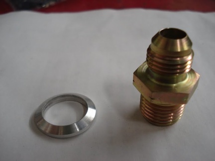 [/caption]
Here is a list of the parts for the AN version of the power steering hoses:
[tr][td]Qty[/td][td]Description[/td][td]Manufacturer[/td][td]Supplier[/td][td]Part #[/td][/tr][tr][td]1[/td][td]Fitting, Straight, AN Flare to Metric, Aluminum, -6 AN to 16mm x 1.5 Male O-ring seal[/td][td]Russells[/td][td]Summit[/td][td]RUS-648060[/td][/tr][tr][td]1[/td][td](P/S Pump – alternative to line item above)
Fitting, Straight, AN flare to Metric, Steel, inverted flare, -6 AN to 16mm x 1.5 Male Washer, Aluminum
(requires fitting + washer)[/td][td]Lee Power Steering[/td][td]Lee Power Steering
818-768-0371[/td][td]Fitting: 40810
Washer: 80520[/td][/tr][tr][td]1[/td][td]Fitting, Power Steering Pressure Port Adapter, -6 AN Male to 11/16-18 in. Inverted Flare, Aluminum, Blue[/td][td]Earls[/td][td]Summit[/td][td]EAR-991950ER[/td][/tr][tr][td]1[/td][td](P/S Box Alternative to line item above)
-6 AN TO 11/16 INVERTED FLARE[/td][td]Aeroquip[/td][td]Summit[/td][td]AER-FBM2965[/td][/tr][tr][td]1[/td][td]Fitting, Power Steering Low Pressure Return Port Adapter, -6 AN Male to ½-20 inverted flare, P/S box)[/td][td]Earls[/td][td]Summit[/td][td]EAR-991946ERL[/td][/tr][tr][td]1[/td][td](P/S Box Alternative to line item above)
FLARE FITTING 5/8-18*[/td][td]Aeroquip[/td][td]Summit[/td][td]AER-FBM2964[/td][/tr][tr][td]1[/td][td]Fitting, Hose End, Power Steering 45 Degree, -6 AN Hose to Female -6 AN, Steel, Nickel Plated[/td][td]Russells[/td][td]Summit[/td][td]RUS-620411[/td][/tr][tr][td]1[/td][td]Fitting, Hose End, Power Steering, 90 Degree, -6 AN Hose to Female -6 AN, Steel, Nickel Plated[/td][td]Russells[/td][td]Summit[/td][td]RUS-620421[/td][/tr][tr][td]1[/td][td]Hose, Powerflex, Braided Stainless Steel, -6 AN, 3 ft. Length[/td][td]Russells[/td][td]Summit[/td][td]RUS-632600[/td][/tr][tr][td]1[/td][td](Hose Alternative to line item above)
#6 Blue AQP pressure hose 6 feet[/td][td]Aeroquip[/td][td]Summit[/td][td]AER-FCG0606[/td][/tr][tr][td]1[/td][td](Optional adapter to reservoir tube) Fitting, -6 AN Male to 3/8 in. Tube, Aluminum, Red/Blue[/td][td]Russells[/td][td]Summit[/td][td]RUS-639210[/td][/tr][/table]*Note: Some power steering gear boxes use ½-20 and some use 5/8-18 on the return. So check yours before ordering.
This list includes the necessary adapters to attach the hose to your power steering box. The steel AN fitting hose ends are necessary for the high pressure hoses in this case. It is a bit expensive but the bling is nice, and in any case, you can make it yourself (and replace it yourself any freakin’ time you want!). No blank looks from parts counter people! The last row, listing the second option of #6 Blue AQP pressure hose, indicates sx feet, which is about right for running the pressure hoses to a hydroboost set-up.
On the low pressure side the attachment is a slip fit with hose clamp at the reservoir. If you are installing a power steering cooler, this is the line to splice for inserting the cooler. If you like you can dress up the return line with braided hose to match the pressure side. An AN -6 to 3/8” tube adapter can be used on the reservoir tube once the flared nipple is cut off. To prevent stress from fracturing the plastic tube and allow the tube adapter to be tightened properly run a drill bit through the tube to slightly enlarge the inside diameter to fit a short section of 5/16” steel tube. A 45 degree hose end mates nicely onto the tube adapter.
(5) Fan and Fan Shroud
Fan. The Explorer fan and clutch assemblies are a big reasons for doing the conversion. Not only can it move a lot of air when it kicks in, but unlike any other mechanical fan arrangements out there, it leaves lots of room between the fan and radiator. It is simply the best mechanical fan option for early Broncos
The Explorer fan is specific to the 5.0 Explorer and is a clutch type. So it consists of a fan that attaches to a clutch unit. And the clutch unit attaches to the end of the water pump. A 4.0 V6 clutch and fan will also work in a pinch if you can’t find the 5.0 parts in working order. The 5.0 clutch will not mate to the 4.0 fan, nor will the 5.0 fan mate to the 4.0 clutch. But the entire assemblies for either the 5.0 or 4.0 are interchangeable. In other words, the both assemblies thread onto the end of the water pump.
The clutch unit attaches to the front of the water pump with a large threaded collar/nut on the back side of the fan clutch housing. The nut is large and requires a very larger pair of otherwise very thin channel-lock type pliers. A large crescent wrench would be perfect, but all crescent wrenches are two thick, if that gives you an idea of the problem. You can hold the water pump shaft with a loose serp belt wrapped around the water pump pulley, or you can see if the installed belt grips well enough to allow you to tighten the nut sufficiently.
Then there are actual tools made for the Explorer serpentine belt maintenance (Fig. 8). In addition to the tool for belt tension release, there are a couple of tools made for the removal of the clutch fan assembly. There is a thin metal open-single-end wrench-shaped tool for the nut that holds the assembly on the water pump, and a special tool that grabs 2 of the 4 water pump pulley bolts so the fan/clutch assembly can be removed more easily. The nut tool supposedly can be found at a parts store with enough looking. The thread is standard (right hand).
[caption id="attachment_1426" align="aligncenter" width="500" caption="Figure 8. Tools made for work on the pulley tensioner and fan clutch assembly. Most of these can be substituted with ingenuity, but#4 is especially nice if you have access to one. (1) tensioner wrench and (2) narrow socket used to release tension on the serpentine belt tensioner so the serpentine belt can be removed (Performance Tools W84010). The scissors-shaped tool (3, K-D Tools 3471) is designed tool to grab 2 of the 4 water pump pulley bolts so the fan/clutch assembly can be removed more easily. And the Fan clutch wrench (4, Performance Tools W80585) is used to loosen the nut that holds the clutch assembly onto the water pump."] [/caption]
Fan Shroud Addition. This is optional. The Explorer mechanical clutch fan sits on a water pump that is already shorter than a ’87-’93 Mustang 5.0 water pump. Add to that the fact that the timing cover is thinner because there is no fuel pump boss, and the result is a fan that sits back considerably farther than even the generous clearance of the stock 302 in most Broncos. This means that the fan does not quite sit inside the fan shroud. To be effective, fans should be at least 1/3 into the fan shroud. If you have a stock fan shroud, the new Explorer fan may not be able to work at its best efficiency if it does not sit deeply enough in the shroud and cannot draw air through the radiator correctly. Some people find that this is not a problem. So check and see what clearance your set-up has and determine if you need to add and extension to your existing fan shroud. Normally an add-on would look cobbled together. But we can add a simple-to-make piece that attaches to the factory shroud with 8-32 x ¾ Phillips head bolts and nuts (Fig. 9A &B). As mentioned earlier, this may not be necessary in every case. But there it is if you need it.
Another option is to purchase a fan shroud designed for this conversion such as the Ron Davis Racing Radiators Explorer 5.0 Early Bronco fan shrouds. They have two models available: one for 0-1” of body lift and one for 2-3” of body lift.
[caption id="attachment_1427" align="aligncenter" width="500" caption="Figure 9A. Template for optional factory shroud extension using thick aluminum sheet metal. It is best to use this to make a cardboard or paper template and check dimensions against your fan shroud. After checking dimension, transfer the template to a piece of thick aluminum sheet metal and cut. Sand the edges to smooth them out and give the whole ting a brushing with steel wool. Fit to the shroud, drill holes for 8-32 x " bolts and attach."] [/caption]
[caption id="attachment_1428" align="aligncenter" width="499" caption="Figure 9B. The finished shroud wraps around the existing factory shroud and extends it about 2 inches."]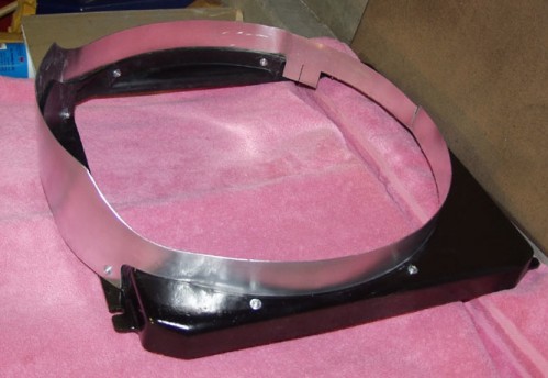 [/caption]
(6) Radiator hoses
Reverse Inlet/Outlet Radiator. If you run a radiator with reversed inlet and outlet, then the standard Mustang hoses are the ones you want. All that is required is some trimming to shorten them to fit. (The original Explorer hoses use other diameters and routing that does not work.) Also look out for hood clearance on the upper hose. Usually trimming the engine end of the upper hose allows the hose to sit low enough to avoid the hood or hood cross-brace. In case it is not otherwise clear, the hood cross-braces were designed specifically so as to interfere with the Explorer serpentine set-up on early Broncos, or so it would seem.
Stock Bronco Radiator. There are a couple of ways to go for both the upper and lower hoses. On the lower hose, to use the stock radiator, you can make a crossover tube like the one outlined in the www.AZbronco.org website, or purchase one from BC Broncos (Fig. 9C). This will allow you to use the stock part number Bronco radiator hoses. They are mounted backwards and do require some trimming but they do work quite well.
[caption id="attachment_1429" align="aligncenter" width="500" caption="Figure 9C. Crossover hose option for use if you are running an original Bronco radiator instead of the 5.0 (“reversed inlet/outlet) radiator."]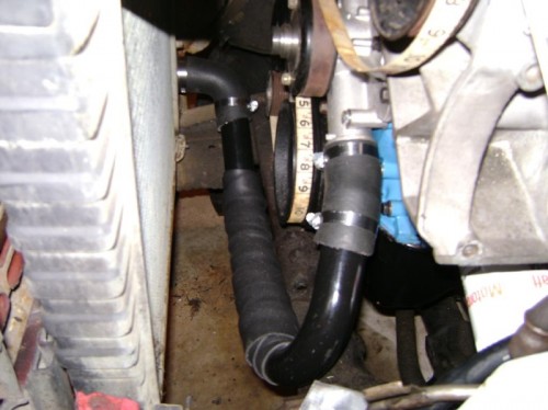 [/caption]
On the upper hose, many people have found that an early model GTO upper radiator hose works. Another clever way is shown in Figure 9D. This uses combination of the GTO hose and a E71317 Radiator hose from advance auto (Dayco 713217, rockauto.com says it is for a 1987-1997 F-250) with a muffler coupler splicing the two together, advance number (548519, 1-1/2 x 1 -1/2) . This routes the upper hose around the back side of the power steering bracket, so it will work if this area is not already populated with other stuff in your application.
With the 351W block a little trimming of the rubber connector hoses is necessary to get the upper hose to work. For the top hose, many people recommend using an early model GTO radiator hose, but some have trouble getting that to work properly. Another option for the upper hose is a Mr Gasket Flex Radiator Hose Kit from Summit (MRG-11012BL), although it is expensive (around $100 at this writing).
(7) Optional Coil Bracket
This is optional but seems to work well, and it gets the coil off the inner fender, puts it into the flow of air, and it keeps the coil wire from being a small, floppy suspension bridge from the fender to coil. The inner fender is valuable real estate anyway, so why fill it up with a coil if you don’t have to?
Standard Coil. If you are running a carburetor, another option is to mount the standard cylindrical ignition coil to the power steering reservoir offset plate that you made up for hood clearance reasons noted previously. Figure 10A pretty well shows how to do this.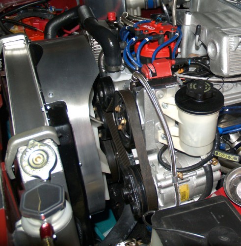
TFI Coil. You can easily make out the small aluminum bracket that to fit the coil on top of the dead space over the power steering pump (Fig. 10B). To make one, start fiddling with a piece of cardboard until you get a shape that fits three of the bolts at various places around the pump bracket. Then cut some sheet metal. Mounted in three places it is strong enough that you can grab the coil and rock the whole vehicle back and forth. Or start with Figure 11 which shows the dimensions for making one up.
[caption id="attachment_1432" align="aligncenter" width="500" caption="Figure 10B. If you are running a carbureted engine, here is the coil attachment for a standard cylindrical coil. Simply attach it to the top of the power steering reservoir offset plate."]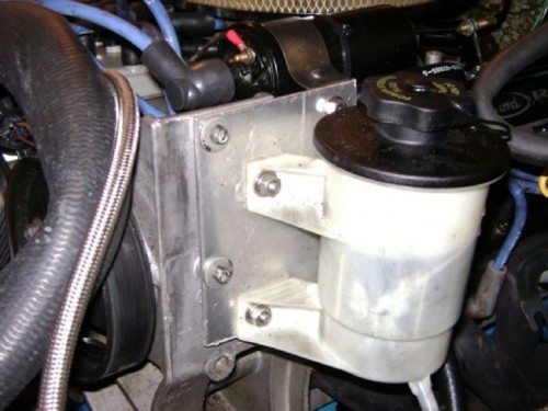 [/caption]
[caption id="attachment_1433" align="aligncenter" width="446" caption="Figure 11. Template for making an optional sheet metal bracket to hold the TFI coil on top of the empty space over the power steering pump."]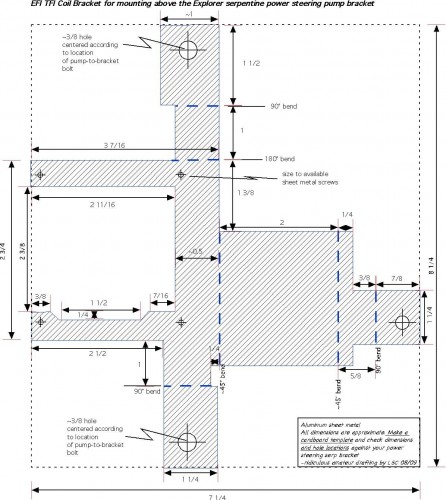 [/caption]
(8) Belts and Belt Routing
A/C Compressor versus Compressor Delete. Figure 12 is a simple reference diagram showing the arrangement of the belts on the pulleys. If you plan on deleting the A/C compressor, then simply leave it off and use a shorter belt like a Gates K060825 (or Goodyear 4060832) on a 302/5.0. Obviously, if you keep the A/C compressor, then you can just ask for a belt for 5.0 Explorer/Mountaineer. What a thought.
If you have a 351W you will have to use a longer belt since the deck height on a 351W is taller and the heads are further apart. To find the correct size you can use the “long-string method” and follow the belt routing (Fig. 12, 13), take the measurement to NAPA, and have them find the closest belt to that measurement. One of us found that an 87" belt worked. The part number is K060870, the 6 representing the number of grooves in the Explorer pulley and the 870 being the length in inches (87.0").
[caption id="attachment_1434" align="aligncenter" width="388" caption="Figure 12. Diagram showing the belt routing."]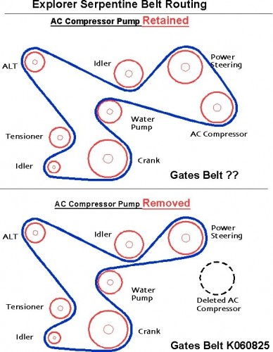 [/caption]
[caption id="attachment_1435" align="aligncenter" width="500" caption="Figure 13A. Photo of belt routing without A/C compressor."]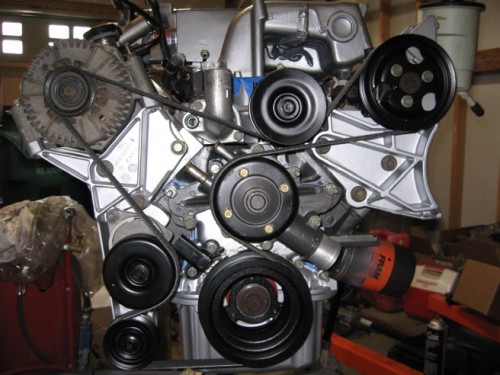 [/caption]
[caption id="attachment_1436" align="aligncenter" width="500" caption="Figure 13B. Method for measuring the belt size for conversion without A/C compressor."]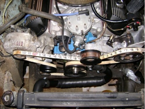 [/caption]
Belt Replacement. How do you “loosen” the tensioner so that you can get a new belt on? Use a long pull-handle with a ½ inch socket. Or you can use the tool made for the job (Performance Tools W84010, see Figure 7). Using the nut on the front of the tensioner pulley, lever the tensioner pulley in the “loose” (counter clockwise) direction while slipping the belt off. The tensioner has a couple of tick marks on it to show when the belt is getting too stretched. When the marks line up indicating maximum stretch of the belt, it needs to be replaced. What will they think of next?
Pulley Maintenance. As many of these accessories have 150,000 plus miles on them by now, the pulley’s are usually worn out. You can either purchase new replacement pulleys, or clean up the original pulleys and replace the bearings. Replacement bearings can be found for as little as $2 each. Motor City brand bearings (part number is SL-203-FF) are good for this. The 203 number is the cross reference to use for different quality/ brand bearings. The bearings can simply be pressed out and back in. If you don’t have a press, you can use an appropriate sized socket and a 3 lb. hammer and drive them out and back in.
(9) Electric Fuel pump
If you are running EFI, then you are likely using electric pumps anyway. But if you are running a carbureted engine then a Carter #4070 is a popular low-pressure pump with a proven durability. The simplest set-up would be to install the electric pump inline where it can draw from either full tank, but as far back as possible. Everybody handles this a little differently, so it is probably best to go to the ClassicBroncos.com forum and search for discussions about how people have installed these. Things to consider including are a fuel filter before the pump intake side (a good idea) and an optional oil-pressure controlled power source, or at least an inertia switch. Adding an electric fuel pump is fairly easy, but there are so many ways to handle it, depending on the particular Bronco in question, that it is really best to read up in the forums if you are in doubt how to go about adding one.
(10) Torque Specs
Timing cover 12-18 ft-lbs
Cam gear bolt 40-45 ft-lbs
Water pump 12-18 ft-lbs
Balancer bolt 110-130 ft-lbs
Sources for Parts
• Damper Dudes to rebalance 302 28 oz crankshaft damper: www.damperdudes.net
• Driven Auto Parts crank shaft adapter pulley for 302 28 oz balancer: http:www.drivenautoparts.com
• Pulley bearings: Grainger, #NTN 6203LLBC3/5C, $8.72 ea at this writing
• Ron Davis fan shroud: http://www.rondavisradiators.com
• Summit Racing: http://www.summitracing.com/
• JEGS: http://www.jegs.com/
• RJM Fuel Injection Technologies, 4G wiring diagram, and 4G alternator accessories: http://fordfuelinjection.com/
• BC Broncos, cross-over tube for standard inlet/outlet radiator: http://www.bcbroncos.com/store/product_info.php?cPath=132_48&products_id=579
“Additional reading”
• For some more pictures, go to LeftCoastBroncos.com http://leftcoastbroncos.com/Pictures/Projects/Explorer%20Serpentine%20Setup/index.html
where there are a bunch more pictures from practically every angle.
• another tech discussion is on the NorCal site (courtesy of thegreatjustino): http://www.norcalbroncos.com/forum/showthread.php?s=7de9f16bf3dacce905141cf47bd94aaa&t=1150
• And another article on the conversion, is in Bronco Driver March/April 2008, p.67.
• Reference Repair Manual: Storer, Jay, and John Haynes, Ford Explorer (’91-’01) Automotive Repair Manual. Haynes Publishing Group, Automotive Manual Series, No. 36024, 2005.
• And don’t forget to search the threads in ClassicBroncos.com for various specific questions and discussions about the Explorer serpentine conversion.
This ClassicBroncos.com tech article covers the steps necessary to install a serpentine belt drive system on your Bronco (Fig. 1) using parts from a ’96-’01 model Ford Explorer or Mercury Mountainer with 5.0 engine. Although the discussion below appears long and involved, the conversion is actually fairly simple. The length of the tech discussion is simply to make sure we to cover each of the main components, the variations in how to handle them according to what engine you are using (302, 5.0, 351), and the usual array of questions that come up about each step regarding parts and fitment. Many Bronco owners can just go to the parts lists, and skim through the sections on power steering hoses and fan shrouds. Other may want to read the whole thing just to make sure they are not “going in blind” and missing something, especially since there are a few points that may not be obvious when you start.
[caption id="attachment_1388" align="aligncenter" width="500" caption="Figure 1. Example of the Explorer 5.0 serpentine belt system installed in an early Bronco. Note that all the accessories are mounted high, instead of being buried in the dark reaches of the engine bay. This particular example is on a 5.0 Ford Racing crate motor. (The A/C compressor bolts are close to the inner fender, so keep that in mind; you may want to have the compressor in place before bolting the bracket up. Access holes in the inner fender, filled with rubber plugs would be nice so you can remove it later if need be.)"]
[/caption]Finally, all six of the authors have contributed solutions for a wide range of the installation questions that come up for stock 302, 5.0, and 351, using various radiators and other commonly differing components used in early Broncos. So, if there are any specific questions not addressed in the following, it is probably best to simply post the question on the ClassicBroncos.com Bronco Tech forum under the heading “Explorer Serp Tech Help”. Since there are many others who have done this conversion, you will get answers from the person(s) who can bring the most experience to bear on your question.
A Few FAQS:
• Does this article tell me how to install an Explorer Serpentine drive on an older 302? Yes
• Does this article tell me how to install an Explorer Serpentine drive on a 351? Yes
• Does this article tell me how to delete the A/C Compressor? Yes
• Does this article tell me how to use another crankshaft pulley instead of the Explorer one? Yes
• Is the Explorer power steering pump strong enough for BIG tires? Yes
• Are there lots of clearance problems? There are several, but the fixes are easy and clean.
Why install a Serpentine Set-up?
The factory V-belt system works fine and can provide adequate service, but the serpentine systems used in most later model engines have several advantages for Broncos:
(1) The factory serpentine systems are on late model vehicles, so the accessories designed for the serpentine systems have benefited from the latest improvements derived from a couple of more decades of experience with design and maintenance of belt-powered accessories.
(2) Late model parts, including the belt-driven accessories, are more widely available and in most cases are designed for heavier loads. The 4G alternator (basically an upgraded 3G designed to fit the Explorer brackets, according to our one and only “RRRAAAYYY”) is a good example. The typical serpentine alternator puts out over four times more amps than the original alternators. The 4G is so potent that it has even been used to make a home-built small welder for sheet metal.
(3) Most serpentine systems mount the critical accessories like alternators and power steering pump high up on the front of the engine, out of the way of road spray, salt, water, and heat and are easier to access and maintain.
(4) No one can argue with the fact that since serpentine systems use a tensioner to maintain the belt tension, and use only one belt for the entire front of the engine, the ability to easily install the belt, in most cases in a matter of minutes, and to maintain the correct tension, is made a lot easier. And you do not have to jack on the side of any accessory to tighten a belt, or guess at the right tension (which most of us probably set too tight anyway).
(5) The Explorer bracketry is stiffer than conventional V-belt brackets and thus the accessories are held in better alignment to each other and to the engine. The more rigid structures also reduce noise, vibration, and harshness in the power train.
(6) Finally, to put the durability and functional superiority in perspective, the Explorer engine cooling, A/C system, and electrical accessories were designed to provide dependable, low maintenance and carefree service to one of the most demanding service situations, the SUV-driving soccer mom! Some automotive engineers will tell you that is not just hyperbole to say that compared to the demands imposed by that situation, off-roading is benign.
Why the Explorer Serpentine Set-up in particular?
The Explorer 5.0 serpentine belt system is one of two most common ways to add a factory serpentine set-up to the small block engines used in early Broncos. The other popular choice is the Mustang 5.0 serpentine belt system. The Explorer has a few advantages. First, it uses a mechanical clutch fan that is capable of impressive cubic-feet-per-minute (“CFM”) air movement through the radiator. Many people claim that it is the best mechanical fan option out there for early Broncos. The Mustang 5.0 serpentine arrangement, on the other hand, puts the fan closer to the radiator than the stock Bronco configuration. During off-roading when the engine and frame flex relative to the body, the fan can (and will!) come into contact with the radiator if the clearance between the two is too small. Because the Explorer timing cover is shorter (it does not have a fuel pump adding to the depth of the cover) the fan is much farther away from the radiator than the typical Mustang 5.0 serp set-up, so fan clearance is not a problem. In fact, it is almost too far away (see below). But it turns out that it is easier to fix that than to fix a fan that is too close.
The Explorer power steering pump is no slouch either. In fact it is very similar (not identical in output) to the power steering pump found on Superduty trucks. So if you are wondering if it can handle those big meats on your rims, be assured that it is a good pump. The 4G alternator on the Explorer set-up is the cream of the crop, and puts out a lot more amps than the original alternators that came on Broncos.
And the original Explorer A/C compressor will work with most of the 134a-based A/C systems such as Vintage Air or BC Bronco’s A/C kit. So if you have A/C on your list, it will work just fine. The Explorer compressor is a Visteon model FS10. If you need an electrical connector for the A/C compressor you can find it at NAPA, Echlin part #ACC100. If you don’t want the A/C compressor, then you can easily delete it, as will be shown below.
In more subjective terms, the Explorer serpentine system and accessories are more truck-like in their size and casting strength. Finally, the Explorer serp set-up beats aftermarket serpentine systems simply because it was designed specifically by the manufacturer for the small block Ford, is made of durable castings, and parts, belts, and accessories are readily available over the local parts counters. And to many of us, the brackets just look better. Additionally, most aftermarket serpentine systems still require manual tensioning of the belts using a threaded turnbuckle or strut arrangement; easier than V-belts, but not as nice as the factory spring-loaded tensioning system which loads the belts precisely to factory specifications.
What are the disadvantages of the Explorer serpentine set-up?
Depending on your point of view, and some things that you may want to do that can’t be done easily with the Explorer serp brackets, the Explorer serpentine set-up may be considered as having some disadvantages. In terms of availability, it has been less common than the Mustang 5.0 serpentine system, so it is may be less available in salvage yards, which could be a problem with finding one. (Some of us would say “non-existent”, but that can be fixed; see below.) However, in recent years, as the 5.0 Explorers have started to appear in the salvage yards, the availability has increased greatly. This disadvantage of limited availability may be changing to an advantage as late model Explorers are becoming more common in salvage yards these days than ’87-’93 Mustangs. Explorers were the number one trade-in in the Cash-for-Clunkers program, which may correlate with salvage yard appearances somewhat in the next few years.
The lower idler pulley is close to the cross member on the frame, which will need to be looked at carefully. There are a couple of things outlined below that can be done to make sure this is not a problem. And some people feel that since the power steering hoses will need to be fabricated, then that can be another dollar sink. But it is really not expensive and has the additional advantage that you can make your own hoses easily, as will be shown below, so others of us think that is a big advantage.
5.0 versus 302/351 differences. One issue that comes up early in the conversion is the fact that the lower crankshaft pulley on the Explorer 5.0 is integrated with the crank balancer. Although the 302/5.0 small block engines are the same displacement, the thing that is different (other than firing order and a few other details) is the balance. Pre-1981 302s and all 351Ws use a 28 oz. external balance, and 1981-up 5.0s use a 50 oz external balance; this means they use different harmonic balancers and different flywheels. Late model engines can simply bolt on the Explorer balancer because the Explorer engine is a “5.0”. But what do you do if you have an earlier small block, a “302” or a 351? To adapt the Explorer crank pulley/balancer to a 28 oz. engine you can do one of four things: (1) have a machine shop rebalance your existing Explorer balancer, (2) you can go to www.damperdudes.net, which does an excellent job, and for $115 total will rebuild, rebalance, and ship your balancer in about a weeks time, (3) if you are doing a build on an engine you could have your crankshaft and flywheel re-balanced to 50 oz external balance, or (4) call Randy at www.drivenautoparts.com who has an adapter pulley to bolt on to your existing 28 oz. 3 bolt balancer. His pulley is right at $75 (at this writing) and is a very nice piece.
Since the Explorer timing cover does not have a fuel pump boss, you will need to convert to an electric pump. This may not be such a bad thing, as good mechanical pumps are getting hard to find, and many are cheap, quality control is low, and may or may not last long either. So going to an electric can be a blessing. They are pretty reliable and nearly bomb-proof these days. Finally, the Explorer has an integral mechanical clutch fan, so it disengages at highway speeds, but runs during slow speed crawling, pulling more air than an electric, and it is excellent of course. The difficulty is that when swapped into an early Bronco the fan may not be covered enough by the stock radiator fan shroud. As a general rule fans need to be slightly inside the shroud or they will pull air from the sides instead of pulling it through the radiator. The fan should be at least a third of the way inside the shroud. Half way in is better. To accommodate this with a stock shroud, some sort of shroud extension must be installed. This is no problem, as will be shown, but it is just another step necessary in the proper installation. Some who have done the conversion do not appear to require it, others do. So it is something to consider, especially if your cooling system tends to be marginal on hot days.
Parts Needed for the Conversion
As far as the brackets go, it is easiest if you find the complete serpentine brackets and pulleys on a 5.0 Explorer/ Mercury Mountaineer (1996-2001) in a salvage yard and remove it yourself. Getting the bolts and making sure you have all the miscellaneous pieces like the clutch fan keeps the project simpler. If you are not junk yard savvy, don’t have the time to go hunting, or you live in a part of the world where, judging from their availability (or lack thereof!) 5.0 Explorers apparently did not exist (one state may have tons of them and the next state over there are none) you can get on line and search the nation’s used car parts businesses for a set-up. There are several used parts search systems on the internet wherein you specify what you are looking for and, if someone has that in their yard, they send you a note. That’s what one of us did and found one in Cleveland. The cost will probably be higher, with prices ranging from $100-$600. But if the search is taking too long, frankly the higher price is worth it just to be done and finished. (You will not find an aftermarket serpentine drive any cheaper, either, and they have the above noted issues anyway.) Life is too short to spend it looking for the perfect deal. Also, if any one part is not available during your search, with the exception of some obvious parts, you can just go to the parts store and buy the darn things.
Collection of all the main factory parts that you will need in order to convert your Bronco to the Explorer serpentine belt drive system. Note: some years of Explorers came equipped with a steel fan, which is also suitable for this conversion. Below are the parts you will need. (And Figure 2 is a picture of the main components that you will want to acquire.)
• Explorer short timing cover and water pump with pulley
• Explorer crank pulley and harmonic balancer (optional, see below)
• Passenger side alternator bracket with tensioner and lower idler pulley
• Driver side power steering and A/C compressor bracket with upper idler pulley, power steering pump, and power steering reservoir
• Explorer clutch and fan
• Make sure you get ALL of the mounting bolts as they are nearly impossible to find aftermarket (if you can’t, see the sizes listed below and see what you can come up with)
Then there are a few items that will be needed to complete the conversion
• Serpentine belt for model year of serp brackets and accessories (there is some variation in pulley designs)
• Felpro TCS 45449 Gasket kit including water pump, timing cover, oil pan end seal and front crankshaft seal (about $12)
• You will need a new high pressure hose for the power steering, because the stock Explorer hoses will not work for our application, but the solution for those will be listed later
• (optional) Some thick aluminum sheet metal (best sourced from a local metal supplier, not the hardware store stuff) and miscellaneous small 8-32 x ¾ screws/nuts/washers to make a fan shroud extension
Installation Overview
The Explorer serpentine system is a mostly bolt-on operation. But like most custom installations there are a few things that need to be considered (in other words, fabricated) if you are to do the job right or avoid any unnecessary surprises. The installation can be broken down into nine main components and steps that you will need to deal with, most of which are fairly trivial:
(1) Timing Cover/Crank Pulley: Installing the Explorer short timing cover, water pump, and crankshaft pulley-harmonic balancer
(2) Accessory Brackets: Bolting on the two accessory brackets and the accessories (alternator, power steering pump, and (optional) A/C compressor)
(3) Alternator wiring: Converting the wiring to the Explorer 4G alternator
(4) Power Steering hoses: Plumbing the power steering pump to your power steering gear
(5) Fan/Radiator shroud: Attaching the Explorer clutch fan and accommodating the increased distance between the fan and the radiator with fan shroud modifications
(6) Radiator Hoses: Depending on whether you are using a stock radiator or a “reversed” inlet/outlet 5.0 type radiator, there are a few options for radiator hoses
(7) Miscellaneous Options, like the coil mounting option.
(8) Belts: Depending on whether you keep the A/C compressor or remove it, or whether you are doing the conversion on a 351, there are some alternatives to the stock Explorer 5.0 belt.
(9) Electric fuel pump: Installing an electric fuel pump (the Explorer short timing cover does not have a mechanical fuel pump boss)
(1) Explorer timing cover and pulley
[caption id="attachment_1390" align="aligncenter" width="400" caption="Figure 3a. Typical 5.0 Explorer timing cover and integral balancer-crank pulley. You will want to substitute the gold piece in this picture (crank position sensor, which you will not need) with a simple timing pointer (see Figure 4)."]
[/caption]Cover. The timing cover and the pulley (Fig. 3A) are unique to the Explorer 5.0. The cover does not have a fuel pump boss and the crank pulley is integral to the harmonic balancer. So you will need to source these to get started. (See below for some options.) These come up on EBay from time to time (at least for a while when Ford Racing was offering a new 5.0 that had the Explorer timing cover and Mustang guys would buy them and sell the timing cover and pulley to go with the Mustang style serp instead). Or if you are lucky enough to have a 5.0 out of an Explorer you are good to go.
Installation is pretty much like any Ford small block timing cover, so follow all the rules on that, especially getting the crankshaft seal up to spec if its old. If you have a fuel pump eccentric for a mechanical fuel pump it will need to be removed and the cam pin may need to be cut or ground so the washer sits flush on the cam gear. The cam pin protrudes through the eccentric to lock it to the gear. Late model engines without a mechanical fuel pump may have an L-shaped oil slinger installed under the cam bolt. This would also need to be removed. Also note that some timing gears are wider than stock and may require other modifications to fit under the Explorer cover. For example the cam bolt head in Figure 3A needed to be milled 0.090” to provide adequate clearance. Your best course of action is to check your cam bolt to timing cover clearance prior to final installation of the timing cover.
Also the Explorer water pump is pretty specific and is necessary in order to mount the fan, so make sure you have that. It’s recommended that you purchase a new water pump at the time of installation and not re-use a used pump with an unknown (probably high) number of miles on it. The water pump is especially adapted to the Explorer fan with special threads on the end of the pump shaft and pulley attachment points.
Hopefully you will have gotten a complete cover with the water pump and the attaching bolts. If not, the water pump bolts and sizes are identified in Figure 4A. Water pump pulley bolts are 5/16” - 28 thread, 1/2” long.
[caption id="attachment_1392" align="aligncenter" width="500" caption="Figure 4A. Water pump mounting bolts. Also in this picture you can see the Explorer timing sensor (which you will remove and replace with a timing pointer) at the 10 o’clock position next to the crankshaft pulley"]
[/caption]Crank Pulley . Torque the harmonic balancer/pulley crank shaft bolt to 110-130 ft-lbs. If your engine is balanced for 50 oz., then you can simply swap the Explorer balancer. The balancer is for the 5.0 flywheel so if you are using a 5.0, a 5.0 balanced flywheel will be necessary, too. The right size to get would be from a 1987 F-150 5.0, and runs about 80 bucks at NAPA; Mustang flywheels are too small and have different starter ring gear teeth counts). The Explorer balancer may also be purchased through NAPA if you were unable to get one at the time you acquired the other components of the serpentine set-up.
But there is another option, especially if you are starting with a 302 or 351. The original Explorer balancer is for 50 oz. external balance crankshafts. If your engine is the older Bronco 302 (i.e., pre-1981) or a 351 (all 351Ws are 28 oz. balance), then you should either have the Explorer balancer rebalanced or order the aforementioned adapter pulley. Incorrectly matching 50 oz. and 28 oz. parts can and will cause all sorts of vibration and drive ability problems.
Timing Pointer. The existing timing pointer mounting located at the 11 o’clock position location (actually on the Explorer it is an variable reluctance electronic trigger arrangement, not a timing “pointer”; see picture above of the timing cover) can be used as a timing pointer mounting point. (Note: This may be true for some years but some find that the pulse trigger also has a pointer and it matches the timing marks on the balancer. If so, it can be used as is with the Explorer balancer.) The Top Dead Center (TDC) mark is stamped on the side of the damper in very faint marks like a standard Bronco damper. If you are making a timing pointer to replace the electronic trigger, then the big groove in the pulley is not TDC and should be ignored. To make use of the TDC marking, simply make up a sheet metal pointer to replace it and just mount it to the original holes where the sensor was mounted (Fig. 4B). You can also use a stock 92 Ford EFI timing pointer.
[caption id="attachment_1393" align="aligncenter" width="500" caption="Figure 4B. Here is the timing pointer location, and an example of one that you can make up. Start out with a piece of cardboard and fab it to fit before cutting metal. A piece of aluminum or sheet metal will do fine. The timing marks are not easy to find. Worse still, there is a big groove in the damper that looks like a timing mark but is not. So look carefully."]
[/caption]Early Bronco 302s have the timing pointer at the 2 o’clock position. If you’re retrofitting the serp system to an early 302 with the Driven Auto pulley you will have to re-index your existing balancer marks to use a pointer at the 11 o’clock position. Mr Gasket timing tape, PN 1594, can be used for this. If your balancer is in questionable condition you can replace it with one indexed for the 11 o’clock timing position. Just remember to match the balance of the original balancer.
You can be very precise and make sure that your pointer agrees with TDC as determined via the usual compression stroke method. Or you can go high-zoot and use a degree wheel. Here’s an additional check: The stock Explorer damper has what looks like gear teeth all around the engine-side of the crank pulley. There are 35 of these teeth evenly spaced every 10 degrees around the pulley, and a gap where the 36th tooth would be. The gap is located at 60 degrees before top dead center. Top Dead Center then is located at the sixth tooth from the gap. This should correspond with the location of the actual stamped TDC marks. The pulley is black, and the letters are tiny, so I did not even know they were there. Frankly I could not find the TDC marks until I did this exercise with the teeth on the pulley.
(2) Installing the Ford Brackets
The brackets are thick aluminum castings onto which are mounted the pulleys and the accessories (alternator, power steering pump, A/C compressor, and belt tensioner). These brackets are each held onto the front of the left and right cylinder heads with three long bolts. Almost every (though apparently not all) Ford small block (including aluminum head crate motors) out there have these holes already there, tapped, and ready to accept these bolts and in the sizes that were on the Explorer heads. (There are a few exceptions in which the heads have threads that are smaller, but this is rare.) It is best if you can get the bolts with the serpentine set-up. But if you can’t, the proper sizes are shown in Figure 5A; although these are almost impossible to find in the right lengths and sizes. If you find a bracket set-up without them, the price should be a lot lower (by the cost of the tank of gas you will use trying to find the bolts!) to compensate for this. The alternator bracket may also have a lower bolt that goes to the block just under the head (Fig 5B). This bolt will not line up when used on a 351W. It is not absolutely necessary, but it does provide some more stiffness.
[caption id="attachment_1394" align="aligncenter" width="333" caption="Figure 5A. Location of bolts attaching the left and right serpentine brackets to the front of small block heads. The bolt sizes are shown in case you need to go buy those separately. If you are lucky, you will have gotten those with the brackets. On some brackets there is also another stiffener bolt down behind the tensioner."]
[/caption][caption id="attachment_1418" align="aligncenter" width="499" caption="Figure 5B. This bolt is not used on the 351W. The power steering/A/C compressor bracket is shown on the right (in this view rotated 90 degrees counterclockwise from its mounted position). These represent all the idler pulleys and can be rebuilt with new bearings if your serpentine setup came from a high-mileage engine."]
[/caption]There are no clearance issues with the accessories other than those discussed below despite the width of the serpentine drive arrangement. The A/C compressor bolts are close to the inner fender on the driver’s side, so keep that in mind; you may want to have the compressor in place before bolting the bracket up. Access holes in the inner fender, filled with rubber plugs would be nice so you can remove it later if need be.
Lower Idler Pulley Clearance. The lower pulley on the passenger side of the engine just below the tensioner pulley is in most cases very close to the Bronco front frame cross-member (Fig. 5C). But there is usually at least ½ inch of clearance or more. However, if there is less than ½ inch clearance, the necessary clearance might be attained by a spacer fabricated to slip between the motor mount and the engine block. Or you might get away with “extreme” type motor mounts, which give you on the order of another ¼ inch of engine lift. Or you may (like most of us) have no problem at all. Some people have even notched the frame and “boxed” the notch for strength, but that is an extreme method to be used only if you cannot go higher with the engine. And if you consider it, you need to talk to a professional race car builder or someone with equivalent experience. Frames, even cross members, are not to be messed with lightly.
[caption id="attachment_1419" align="aligncenter" width="500" caption=" Figure 5C. The lower passenger side belt idler pulley can be very close to the frame. There should be a minimum of ! inch clearance. If it is less, the easiest option is to raise the enigine with shims between the motor mount and block."]
[/caption]TFI Module Clearance. The Explorer 5.0 used a distributor-less ignition and was not designed with a standard distributor in mind, so using the Explorer brackets with the typical TFI distributor on an EFI conversion are not designed to allow the range in rotation of the distributor that is needed while timing an engine. The upper serpentine idler pulley support (Fig. 5D) can get in the way of the TFI module that sticks out tangent to the distributor. If the distributor is clocked carefully on installation, there is a “sweet spot” where it will have the necessary clearance throughout any likely arc during timing adjustment. But if this still does not work, it is possible to do some slight clearancing of the bracket just behind the upper idler pulley to get some additional motion. The metal is soft, so this can be done with some careful grinding and shaping to make it look pretty.
[caption id="attachment_1420" align="aligncenter" width="500" caption="Figure 5D. The TFI module can interfer with the serpentine bracket. Soutions include clearancing the bracket slightly or installing the distributor slightly counterclockwise (maybe about 1 tooth over)."]
[/caption]Oil Pressure Sensor Clearance. One more thing that should be checked is the oil pressure sensor. Commonly this will contact the lower part of the driver side bracket near A/C Compressor attachment point. The simple fix is to clock the oil pressure sensor extension tube clockwise (toward the rear of the engine) a few degrees instead of the usual position pointing straight up. This should provide the necessary clearance (Fig. 5E). You may need to back the extension completely out first if it is already tight and clean the threads carefully (this is an oil passageway). Then when you go back in, tighten it enough for a seal using some thread sealer while clocking it to just the right angle.
[caption id="attachment_1421" align="aligncenter" width="500" caption="Figure 5E. View with the A/C compressor not mounted in order to show the oil pressure sensorto- bracket clearance. In most cases, clocking the oil pressure sensor extension housing provides clearance."]
[/caption](3) Alternator
The 4G alternator housing is specifically designed for the Explorer serpentine brackets and attaches with three mounting bolts that are metric, M10 x 75mm with 1.5mm pitch. One option to consider is using one of them to attach your negative battery cable when installing the alternator. This is especially true if you have painted or power coated the brackets. Or you could use the lower stiffener bolt on the passenger side serpentine bracket. In either case, just be sure to also run a good heavy-duty ground strap from the engine to the body.
As far as the alternator itself, the wiring is fairly straight forward. The old external voltage regulator and old alternator harness will need to be removed from the electrical system. The green-red wire that went to the old regulator “S” terminal will be used to provide a start signal to the new 4G alternator “I” terminal. Below (Fig. 6A) is a diagram from Ryan’s EFI site that pretty well says it all. Ignore the charge indicator lamp and the 510 ohm resistor in this diagram; it’s not used on an early Bronco. The next diagram (Fig. 6B) is more of a schematic from the standard Bronco wiring diagram that has been altered to show how this fits into the real-world situation. (Note: We show the battery cable going to the starter directly, but this applies only if you are using a mini-starter. Otherwise it should go through the starter solenoid like it was from the factory.) So the green-red power goes to terminal “I” and a yellow wire goes from “A” to the output terminal, and the output goes directly via a heavy battery cable to the battery positive. That’s it.
[caption id="attachment_1422" align="aligncenter" width="499" caption="Figure 6A. Diagram from Ryan’s web site showing the wiring for a 4G alternator."]
[/caption][caption id="attachment_1423" align="aligncenter" width="500" caption="Figure 6B. Diagram for normal folks modified from the factory drawing that we are all familiar with. The voltage regulator and ammeter are removed from the circuit."]
[/caption]Because the ammeter on the stock gauge cluster is no longer functional once you convert to the 4G alternator (the stock ammeter wiring cannot handle the current output from the 4G alternator), the best thing to do is to try one of the voltmeter conversions that several people have found. These actually fit in place of the ammeter gauge. Or you can just ignore the ammeter gauge for the time being and put a voltmeter conversion on your to-do list for the future.
(4) Installing the Power Steering Pump Reservoir and Hoses
The power steering pump is a good pump for Broncos and it appears to be capable of handling some serious tire sizes. But the hose connections need to be accommodated to the Bronco power steering gear and the remote reservoir usually needs to be slightly re-located.
Installing the Power steering remote reservoir. Unlike the factory pump or popular Saginaw/Delphi pump, the Explorer power steering pump has a remote reservoir. The remote reservoir presents a challenge for many Broncos because it sits too high on the bracket and hits the inside of the hood unless moved down. Like the other clearance issues, some Bronco owners do not find this to be the case. Others with body lifts and extra hood clearance just barely scrap by. So again, you just need to check and see what you have at this point in the conversion.
The reservoir in stock configuration is mounted not-so-remotely next to the pump on the driver side bracket and looks like a cylindrical plastic container with two hoses exiting out the bottom. One goes to the low pressure return, and the other goes to the intake side of the power steering pump. In theory you can mount the reservoir wherever you like, since it is remote. This means just making the hoses longer, maybe mounting it to the firewall should also be an option. But if you have enough hoses inside the engine bay already, the stock location works well enough, and you can instead move the reservoir enough to clear the hood.
To clear the hood in most cases the reservoir needs to be moved down and usually back as well to clear the hood cross-member that just happens to be about where the reservoir top is. You can do this by making a simple offset bracket which consists of a 2 inch by 3 inch piece of aluminum flat-stock with offset holes (Fig. 7A). Try moving the reservoir down and back as far as possible. The limiting factor will be the A/C compressor immediately beneath (unless you are going to delete the A/C compressor).
[caption id="attachment_1424" align="aligncenter" width="500" caption="Figure 7A. Offset the power steering reservoir down at least an inch and back about a half inch using a simple flat plate of aluminum (hardware store) as an adapter. You will want to raise the fluid level an amount equivalent to the drop in height so that the fluid level remains where it would be if the reservoir were left in the stock position. There are limits of course to how high, but increasing the level a bit would help keep the correct amount available to the pump."]
[/caption]Plumbing the Power Steering. On the high pressure side (coming out of the power steering pump) the Explorer uses a metric hose on the power steering pump end (16mm x 1.5 O-ring), while most of our Broncos run power steering boxes that use standard English fittings (for example, commonly an 11/16-18 in fitting on the input pressure side of the steering gear, although you should check as some boxes apparently used a ¾ in fitting; and some use a ½ inch fitting on the low pressure side).
Some people are successful at finding a local hose supplier that can make up the appropriate high pressure power steering hose. But many of us apparently live on a different planet where asking a shop to make a hose would get us blank looks. So being able to make your own is a huge plus here. So a simple solution is to make your own hoses and include an adapter fitting to fit it all to your existing stock (or aftermarket) power steering box. This is simple using AN fittings and special high pressure AN–specific hoses. The basic idea is to make use of AN fittings to make the connection between the metric Explorer pump side and the SAE non-metric steering gear side. And best of all, you can order the parts from any high-performance parts place, like Summit, JEGS, or Lee Manufacturing. Finally, note that there are at least two ways to adapt the hoses to the power steering pump using Russells or Lee Manufacturing components, and you can also use Aeroquip components. Some people find that the Lee Manufacturing adaptor (Fig. 7B) offers a better seal at the power steering pump. Your choice. The table below lists alternatives in a couple of cases, so the table only looks like a long list.
[caption id="attachment_1425" align="aligncenter" width="432" caption="Figure 7B. Lee Manufacturing power steering pump metric 16mm x 1.5-to-AN-hose adapter. The corresponding Russells fitting use a rubber O-ring instead of the flare fitting with metal washer."]
[/caption]Here is a list of the parts for the AN version of the power steering hoses:
[tr][td]Qty[/td][td]Description[/td][td]Manufacturer[/td][td]Supplier[/td][td]Part #[/td][/tr][tr][td]1[/td][td]Fitting, Straight, AN Flare to Metric, Aluminum, -6 AN to 16mm x 1.5 Male O-ring seal[/td][td]Russells[/td][td]Summit[/td][td]RUS-648060[/td][/tr][tr][td]1[/td][td](P/S Pump – alternative to line item above)
Fitting, Straight, AN flare to Metric, Steel, inverted flare, -6 AN to 16mm x 1.5 Male Washer, Aluminum
(requires fitting + washer)[/td][td]Lee Power Steering[/td][td]Lee Power Steering
818-768-0371[/td][td]Fitting: 40810
Washer: 80520[/td][/tr][tr][td]1[/td][td]Fitting, Power Steering Pressure Port Adapter, -6 AN Male to 11/16-18 in. Inverted Flare, Aluminum, Blue[/td][td]Earls[/td][td]Summit[/td][td]EAR-991950ER[/td][/tr][tr][td]1[/td][td](P/S Box Alternative to line item above)
-6 AN TO 11/16 INVERTED FLARE[/td][td]Aeroquip[/td][td]Summit[/td][td]AER-FBM2965[/td][/tr][tr][td]1[/td][td]Fitting, Power Steering Low Pressure Return Port Adapter, -6 AN Male to ½-20 inverted flare, P/S box)[/td][td]Earls[/td][td]Summit[/td][td]EAR-991946ERL[/td][/tr][tr][td]1[/td][td](P/S Box Alternative to line item above)
FLARE FITTING 5/8-18*[/td][td]Aeroquip[/td][td]Summit[/td][td]AER-FBM2964[/td][/tr][tr][td]1[/td][td]Fitting, Hose End, Power Steering 45 Degree, -6 AN Hose to Female -6 AN, Steel, Nickel Plated[/td][td]Russells[/td][td]Summit[/td][td]RUS-620411[/td][/tr][tr][td]1[/td][td]Fitting, Hose End, Power Steering, 90 Degree, -6 AN Hose to Female -6 AN, Steel, Nickel Plated[/td][td]Russells[/td][td]Summit[/td][td]RUS-620421[/td][/tr][tr][td]1[/td][td]Hose, Powerflex, Braided Stainless Steel, -6 AN, 3 ft. Length[/td][td]Russells[/td][td]Summit[/td][td]RUS-632600[/td][/tr][tr][td]1[/td][td](Hose Alternative to line item above)
#6 Blue AQP pressure hose 6 feet[/td][td]Aeroquip[/td][td]Summit[/td][td]AER-FCG0606[/td][/tr][tr][td]1[/td][td](Optional adapter to reservoir tube) Fitting, -6 AN Male to 3/8 in. Tube, Aluminum, Red/Blue[/td][td]Russells[/td][td]Summit[/td][td]RUS-639210[/td][/tr][/table]*Note: Some power steering gear boxes use ½-20 and some use 5/8-18 on the return. So check yours before ordering.
This list includes the necessary adapters to attach the hose to your power steering box. The steel AN fitting hose ends are necessary for the high pressure hoses in this case. It is a bit expensive but the bling is nice, and in any case, you can make it yourself (and replace it yourself any freakin’ time you want!). No blank looks from parts counter people! The last row, listing the second option of #6 Blue AQP pressure hose, indicates sx feet, which is about right for running the pressure hoses to a hydroboost set-up.
On the low pressure side the attachment is a slip fit with hose clamp at the reservoir. If you are installing a power steering cooler, this is the line to splice for inserting the cooler. If you like you can dress up the return line with braided hose to match the pressure side. An AN -6 to 3/8” tube adapter can be used on the reservoir tube once the flared nipple is cut off. To prevent stress from fracturing the plastic tube and allow the tube adapter to be tightened properly run a drill bit through the tube to slightly enlarge the inside diameter to fit a short section of 5/16” steel tube. A 45 degree hose end mates nicely onto the tube adapter.
(5) Fan and Fan Shroud
Fan. The Explorer fan and clutch assemblies are a big reasons for doing the conversion. Not only can it move a lot of air when it kicks in, but unlike any other mechanical fan arrangements out there, it leaves lots of room between the fan and radiator. It is simply the best mechanical fan option for early Broncos
The Explorer fan is specific to the 5.0 Explorer and is a clutch type. So it consists of a fan that attaches to a clutch unit. And the clutch unit attaches to the end of the water pump. A 4.0 V6 clutch and fan will also work in a pinch if you can’t find the 5.0 parts in working order. The 5.0 clutch will not mate to the 4.0 fan, nor will the 5.0 fan mate to the 4.0 clutch. But the entire assemblies for either the 5.0 or 4.0 are interchangeable. In other words, the both assemblies thread onto the end of the water pump.
The clutch unit attaches to the front of the water pump with a large threaded collar/nut on the back side of the fan clutch housing. The nut is large and requires a very larger pair of otherwise very thin channel-lock type pliers. A large crescent wrench would be perfect, but all crescent wrenches are two thick, if that gives you an idea of the problem. You can hold the water pump shaft with a loose serp belt wrapped around the water pump pulley, or you can see if the installed belt grips well enough to allow you to tighten the nut sufficiently.
Then there are actual tools made for the Explorer serpentine belt maintenance (Fig. 8). In addition to the tool for belt tension release, there are a couple of tools made for the removal of the clutch fan assembly. There is a thin metal open-single-end wrench-shaped tool for the nut that holds the assembly on the water pump, and a special tool that grabs 2 of the 4 water pump pulley bolts so the fan/clutch assembly can be removed more easily. The nut tool supposedly can be found at a parts store with enough looking. The thread is standard (right hand).
[caption id="attachment_1426" align="aligncenter" width="500" caption="Figure 8. Tools made for work on the pulley tensioner and fan clutch assembly. Most of these can be substituted with ingenuity, but#4 is especially nice if you have access to one. (1) tensioner wrench and (2) narrow socket used to release tension on the serpentine belt tensioner so the serpentine belt can be removed (Performance Tools W84010). The scissors-shaped tool (3, K-D Tools 3471) is designed tool to grab 2 of the 4 water pump pulley bolts so the fan/clutch assembly can be removed more easily. And the Fan clutch wrench (4, Performance Tools W80585) is used to loosen the nut that holds the clutch assembly onto the water pump."]
[/caption]Fan Shroud Addition. This is optional. The Explorer mechanical clutch fan sits on a water pump that is already shorter than a ’87-’93 Mustang 5.0 water pump. Add to that the fact that the timing cover is thinner because there is no fuel pump boss, and the result is a fan that sits back considerably farther than even the generous clearance of the stock 302 in most Broncos. This means that the fan does not quite sit inside the fan shroud. To be effective, fans should be at least 1/3 into the fan shroud. If you have a stock fan shroud, the new Explorer fan may not be able to work at its best efficiency if it does not sit deeply enough in the shroud and cannot draw air through the radiator correctly. Some people find that this is not a problem. So check and see what clearance your set-up has and determine if you need to add and extension to your existing fan shroud. Normally an add-on would look cobbled together. But we can add a simple-to-make piece that attaches to the factory shroud with 8-32 x ¾ Phillips head bolts and nuts (Fig. 9A &B). As mentioned earlier, this may not be necessary in every case. But there it is if you need it.
Another option is to purchase a fan shroud designed for this conversion such as the Ron Davis Racing Radiators Explorer 5.0 Early Bronco fan shrouds. They have two models available: one for 0-1” of body lift and one for 2-3” of body lift.
[caption id="attachment_1427" align="aligncenter" width="500" caption="Figure 9A. Template for optional factory shroud extension using thick aluminum sheet metal. It is best to use this to make a cardboard or paper template and check dimensions against your fan shroud. After checking dimension, transfer the template to a piece of thick aluminum sheet metal and cut. Sand the edges to smooth them out and give the whole ting a brushing with steel wool. Fit to the shroud, drill holes for 8-32 x " bolts and attach."]
[/caption][caption id="attachment_1428" align="aligncenter" width="499" caption="Figure 9B. The finished shroud wraps around the existing factory shroud and extends it about 2 inches."]
[/caption](6) Radiator hoses
Reverse Inlet/Outlet Radiator. If you run a radiator with reversed inlet and outlet, then the standard Mustang hoses are the ones you want. All that is required is some trimming to shorten them to fit. (The original Explorer hoses use other diameters and routing that does not work.) Also look out for hood clearance on the upper hose. Usually trimming the engine end of the upper hose allows the hose to sit low enough to avoid the hood or hood cross-brace. In case it is not otherwise clear, the hood cross-braces were designed specifically so as to interfere with the Explorer serpentine set-up on early Broncos, or so it would seem.
Stock Bronco Radiator. There are a couple of ways to go for both the upper and lower hoses. On the lower hose, to use the stock radiator, you can make a crossover tube like the one outlined in the www.AZbronco.org website, or purchase one from BC Broncos (Fig. 9C). This will allow you to use the stock part number Bronco radiator hoses. They are mounted backwards and do require some trimming but they do work quite well.
[caption id="attachment_1429" align="aligncenter" width="500" caption="Figure 9C. Crossover hose option for use if you are running an original Bronco radiator instead of the 5.0 (“reversed inlet/outlet) radiator."]
[/caption]On the upper hose, many people have found that an early model GTO upper radiator hose works. Another clever way is shown in Figure 9D. This uses combination of the GTO hose and a E71317 Radiator hose from advance auto (Dayco 713217, rockauto.com says it is for a 1987-1997 F-250) with a muffler coupler splicing the two together, advance number (548519, 1-1/2 x 1 -1/2) . This routes the upper hose around the back side of the power steering bracket, so it will work if this area is not already populated with other stuff in your application.
With the 351W block a little trimming of the rubber connector hoses is necessary to get the upper hose to work. For the top hose, many people recommend using an early model GTO radiator hose, but some have trouble getting that to work properly. Another option for the upper hose is a Mr Gasket Flex Radiator Hose Kit from Summit (MRG-11012BL), although it is expensive (around $100 at this writing).
(7) Optional Coil Bracket
This is optional but seems to work well, and it gets the coil off the inner fender, puts it into the flow of air, and it keeps the coil wire from being a small, floppy suspension bridge from the fender to coil. The inner fender is valuable real estate anyway, so why fill it up with a coil if you don’t have to?
Standard Coil. If you are running a carburetor, another option is to mount the standard cylindrical ignition coil to the power steering reservoir offset plate that you made up for hood clearance reasons noted previously. Figure 10A pretty well shows how to do this.
TFI Coil. You can easily make out the small aluminum bracket that to fit the coil on top of the dead space over the power steering pump (Fig. 10B). To make one, start fiddling with a piece of cardboard until you get a shape that fits three of the bolts at various places around the pump bracket. Then cut some sheet metal. Mounted in three places it is strong enough that you can grab the coil and rock the whole vehicle back and forth. Or start with Figure 11 which shows the dimensions for making one up.
[caption id="attachment_1432" align="aligncenter" width="500" caption="Figure 10B. If you are running a carbureted engine, here is the coil attachment for a standard cylindrical coil. Simply attach it to the top of the power steering reservoir offset plate."]
[/caption][caption id="attachment_1433" align="aligncenter" width="446" caption="Figure 11. Template for making an optional sheet metal bracket to hold the TFI coil on top of the empty space over the power steering pump."]
[/caption](8) Belts and Belt Routing
A/C Compressor versus Compressor Delete. Figure 12 is a simple reference diagram showing the arrangement of the belts on the pulleys. If you plan on deleting the A/C compressor, then simply leave it off and use a shorter belt like a Gates K060825 (or Goodyear 4060832) on a 302/5.0. Obviously, if you keep the A/C compressor, then you can just ask for a belt for 5.0 Explorer/Mountaineer. What a thought.
If you have a 351W you will have to use a longer belt since the deck height on a 351W is taller and the heads are further apart. To find the correct size you can use the “long-string method” and follow the belt routing (Fig. 12, 13), take the measurement to NAPA, and have them find the closest belt to that measurement. One of us found that an 87" belt worked. The part number is K060870, the 6 representing the number of grooves in the Explorer pulley and the 870 being the length in inches (87.0").
[caption id="attachment_1434" align="aligncenter" width="388" caption="Figure 12. Diagram showing the belt routing."]
[/caption][caption id="attachment_1435" align="aligncenter" width="500" caption="Figure 13A. Photo of belt routing without A/C compressor."]
[/caption][caption id="attachment_1436" align="aligncenter" width="500" caption="Figure 13B. Method for measuring the belt size for conversion without A/C compressor."]
[/caption]Belt Replacement. How do you “loosen” the tensioner so that you can get a new belt on? Use a long pull-handle with a ½ inch socket. Or you can use the tool made for the job (Performance Tools W84010, see Figure 7). Using the nut on the front of the tensioner pulley, lever the tensioner pulley in the “loose” (counter clockwise) direction while slipping the belt off. The tensioner has a couple of tick marks on it to show when the belt is getting too stretched. When the marks line up indicating maximum stretch of the belt, it needs to be replaced. What will they think of next?
Pulley Maintenance. As many of these accessories have 150,000 plus miles on them by now, the pulley’s are usually worn out. You can either purchase new replacement pulleys, or clean up the original pulleys and replace the bearings. Replacement bearings can be found for as little as $2 each. Motor City brand bearings (part number is SL-203-FF) are good for this. The 203 number is the cross reference to use for different quality/ brand bearings. The bearings can simply be pressed out and back in. If you don’t have a press, you can use an appropriate sized socket and a 3 lb. hammer and drive them out and back in.
(9) Electric Fuel pump
If you are running EFI, then you are likely using electric pumps anyway. But if you are running a carbureted engine then a Carter #4070 is a popular low-pressure pump with a proven durability. The simplest set-up would be to install the electric pump inline where it can draw from either full tank, but as far back as possible. Everybody handles this a little differently, so it is probably best to go to the ClassicBroncos.com forum and search for discussions about how people have installed these. Things to consider including are a fuel filter before the pump intake side (a good idea) and an optional oil-pressure controlled power source, or at least an inertia switch. Adding an electric fuel pump is fairly easy, but there are so many ways to handle it, depending on the particular Bronco in question, that it is really best to read up in the forums if you are in doubt how to go about adding one.
(10) Torque Specs
Timing cover 12-18 ft-lbs
Cam gear bolt 40-45 ft-lbs
Water pump 12-18 ft-lbs
Balancer bolt 110-130 ft-lbs
Sources for Parts
• Damper Dudes to rebalance 302 28 oz crankshaft damper: www.damperdudes.net
• Driven Auto Parts crank shaft adapter pulley for 302 28 oz balancer: http:www.drivenautoparts.com
• Pulley bearings: Grainger, #NTN 6203LLBC3/5C, $8.72 ea at this writing
• Ron Davis fan shroud: http://www.rondavisradiators.com
• Summit Racing: http://www.summitracing.com/
• JEGS: http://www.jegs.com/
• RJM Fuel Injection Technologies, 4G wiring diagram, and 4G alternator accessories: http://fordfuelinjection.com/
• BC Broncos, cross-over tube for standard inlet/outlet radiator: http://www.bcbroncos.com/store/product_info.php?cPath=132_48&products_id=579
“Additional reading”
• For some more pictures, go to LeftCoastBroncos.com http://leftcoastbroncos.com/Pictures/Projects/Explorer%20Serpentine%20Setup/index.html
where there are a bunch more pictures from practically every angle.
• another tech discussion is on the NorCal site (courtesy of thegreatjustino): http://www.norcalbroncos.com/forum/showthread.php?s=7de9f16bf3dacce905141cf47bd94aaa&t=1150
• And another article on the conversion, is in Bronco Driver March/April 2008, p.67.
• Reference Repair Manual: Storer, Jay, and John Haynes, Ford Explorer (’91-’01) Automotive Repair Manual. Haynes Publishing Group, Automotive Manual Series, No. 36024, 2005.
• And don’t forget to search the threads in ClassicBroncos.com for various specific questions and discussions about the Explorer serpentine conversion.
