• Welcome to ClassicBroncos! - You are currently viewing the forums as a GUEST. To take advantage of all the site features, please take a moment to register. It's fast, simple and absolutely free. So please join our community today!
    If you have problems registering or can't log into your account, please contact Admin.

Can I put my battery ground here? Plus explore alt wiring connections.

joshua

Contributor
Bronco Guru
Joined
Jun 5, 2007
Messages
1,761
I’m starting blind with an old wire harness that was in a bucket, and the explorer front dress.

Can I just run my battery ground to the alternator bracket I’m pointing to in the first picture?

And I’m pretty sure that yellow wire gets looped back onto the alternator wire that feeds back to the positive side of the battery. Lmk if it looks correct in the second picture. But does one of those wires feed the volt gauge in the dash? If so which one? I did buy the voltage gauge to replace the stock amp meter.
 

Attachments

  • IMG_0182.jpeg
    IMG_0182.jpeg
    242.6 KB · Views: 103
  • IMG_0183.jpeg
    IMG_0183.jpeg
    164.7 KB · Views: 99
  • IMG_0184.jpeg
    IMG_0184.jpeg
    212.4 KB · Views: 103

DirtDonk

Contributor
Bronco Guru
Joined
Nov 3, 2003
Messages
51,619
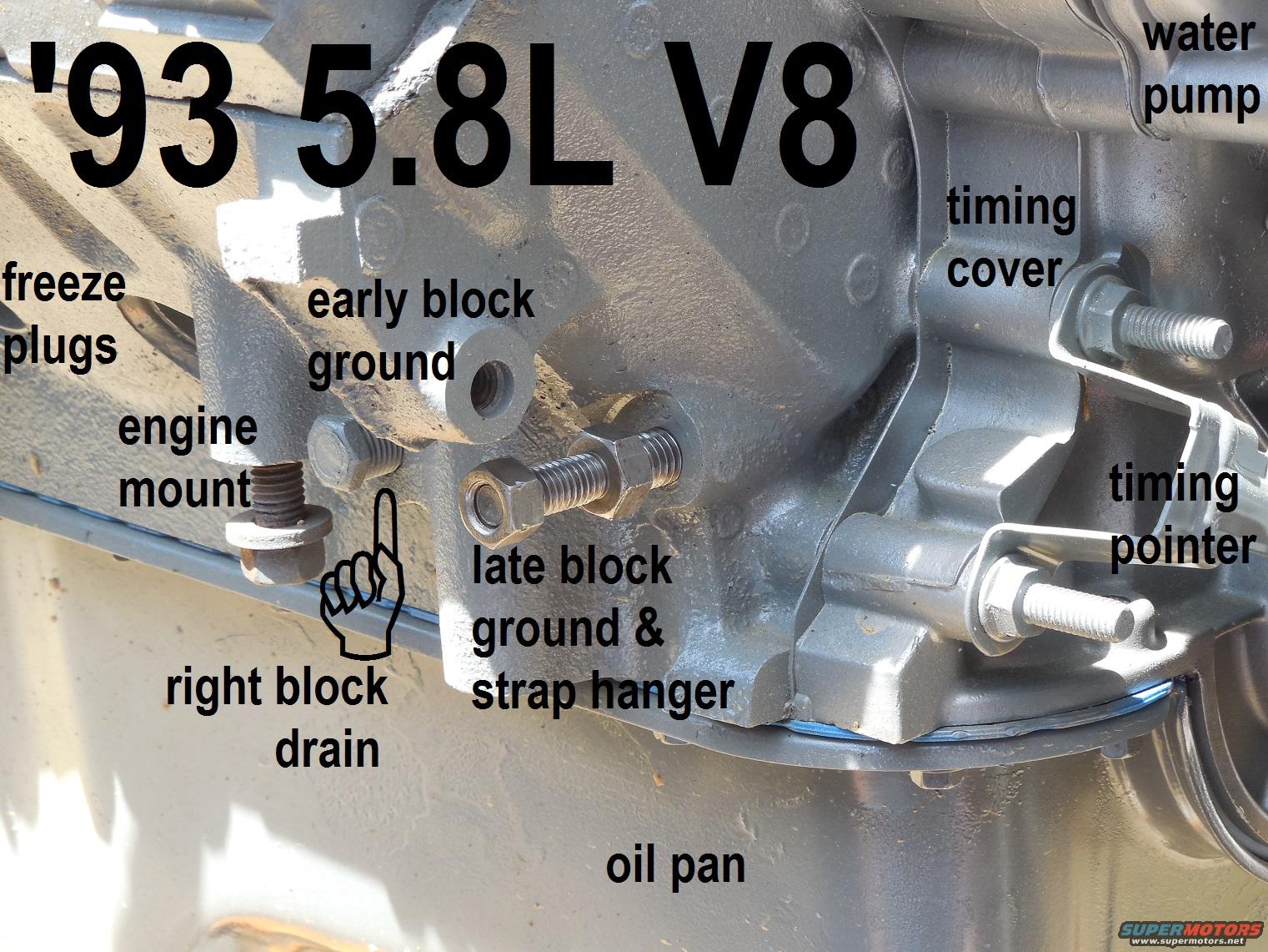
Yes, you can put the ground on that convenient bolt. But I would not. Too much distance between the battery and the starter motor.
And the starter motor is the biggest power hog of them all.
Better to bolt it directly to the engine block and the closer to the starter the better.
Just a general best practice.
 

DirtDonk

Contributor
Bronco Guru
Joined
Nov 3, 2003
Messages
51,619
And yes, most builds I think include the yellow wire, going to the BAT output of the alternator.
However, here again, a best practice would be to run it back closer to the Battery.
Over to the starter relay Battery side, or the Battery side of the Mega-fuse if that’s what you’re using.
 

DirtDonk

Contributor
Bronco Guru
Joined
Nov 3, 2003
Messages
51,619
Since the colors on your regulator plug are incorrect (typical of aftermarket accessories) verify the position rather than the color.
You only need two wires on an explorer 4G, not the typical three of a 3G.
The other wire that you need is not to feed the voltmeter. It is to feed the alternator/regulator power from the ignition switch.
It gets connected to the old green with red stripe wire from the old harness.

Speaking of the old harness, if you still have the yellow wire in the alternator harness on the body side, connect your yellow wire to that one.
Nothing wrong with looping it right over to the terminal of the alternator, and dozens, if not hundreds of members here have done it that way successfully.
I’m just one of those that likes to run it the way the factory did.
 

Steve83

Bronco Guru
Joined
Jul 16, 2003
Messages
9,359
Loc.
Memphis, TN, USA, Earth, Milky Way
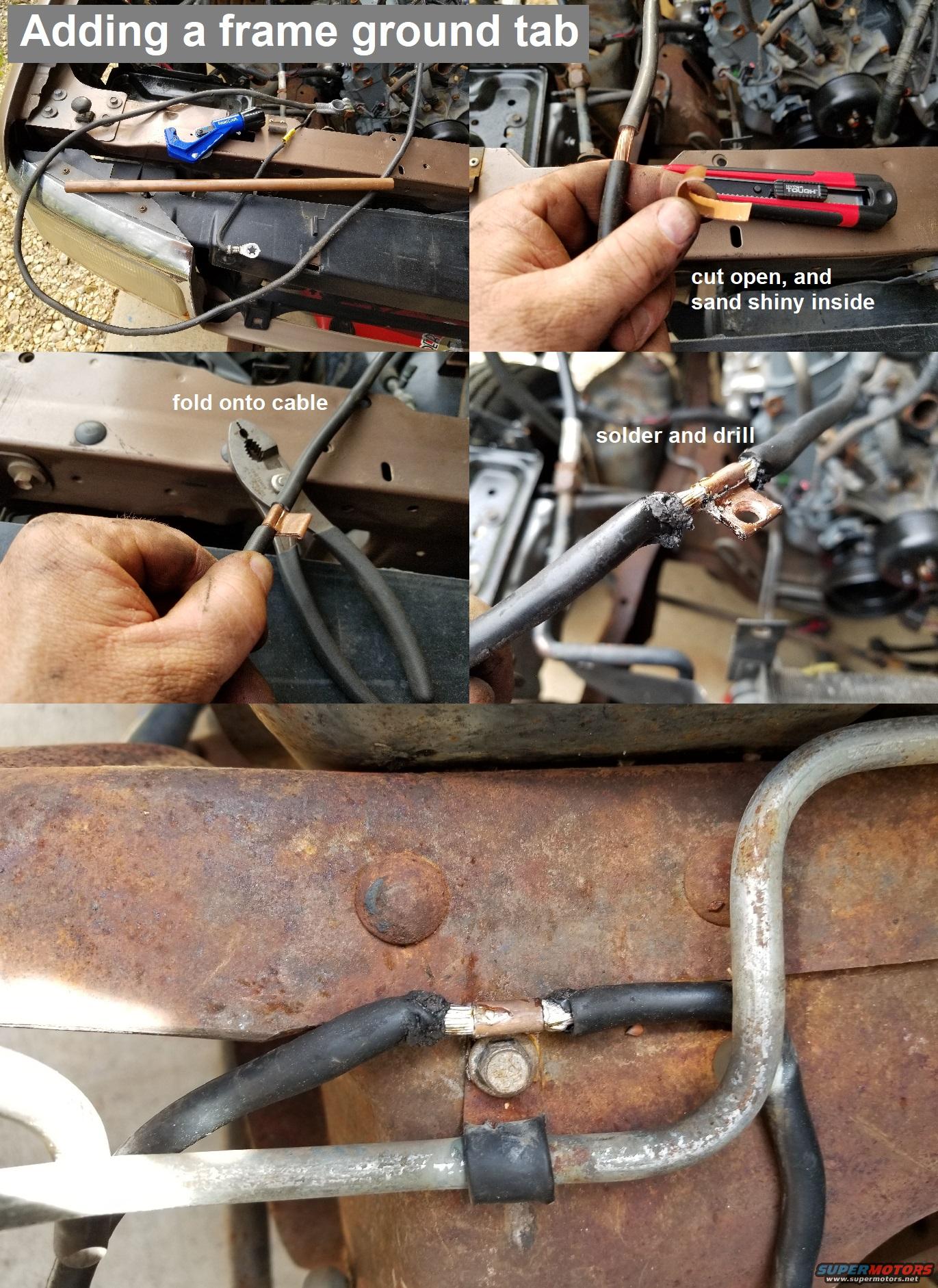
The best way to route it is the way Ford did on later trucks. Basically, add a tab that you can bolt to the frame, and add a ~6~10ga wire that you can screw to the body sheet metal. But bolt the main 4ga cable to the block.

battstartwire9296.jpg


blockgrounds9358.jpg


20200329_144339.jpg
 
OP
OP
joshua

joshua

Contributor
Bronco Guru
Joined
Jun 5, 2007
Messages
1,761
And yes, most builds I think include the yellow wire, going to the BAT output of the alternator.
However, here again, a best practice would be to run it back closer to the Battery.
Over to the starter relay Battery side, or the Battery side of the Mega-fuse if that’s what you’re using.
I’m thinking you’re talking about the wire in this first picture not the second. Or maybe they are the same wire.

And I have no clue where any of the wires go. I took this apart when I was 24 yrs old I’m almost 47 now lol
 

Attachments

  • IMG_0185.jpeg
    IMG_0185.jpeg
    210.8 KB · Views: 73
  • IMG_0186.jpeg
    IMG_0186.jpeg
    150.9 KB · Views: 60

DirtDonk

Contributor
Bronco Guru
Joined
Nov 3, 2003
Messages
51,619
You mean, just like a typical Bronco build.
Like it was just yesterday! Except for the memories going vague that is.😁
 

DirtDonk

Contributor
Bronco Guru
Joined
Nov 3, 2003
Messages
51,619
The yellow wire molded into the ring connector that goes onto the starter relay should be for your horn relay power.
Not the same as the yellow wire going to the four cavity regulator connector for the old regulator.
You can, if using the old wires, depin (or just cut off) the yellow wire from the big connector and connect it to the new yellow wire at your alternator.
Either one would theoretically work, but you don’t wanna mess with the one for the horn relay if you don’t have to.
What year is this Bronco again?

And what I said before, find other pictures of 3G connectors. Maybe Steve’s diagrams show it.
Because the colors are wrong in the new connector you want to make sure that the position is correct.
 
OP
OP
joshua

joshua

Contributor
Bronco Guru
Joined
Jun 5, 2007
Messages
1,761
The yellow wire molded into the ring connector that goes onto the starter relay should be for your horn relay power.
Not the same as the yellow wire going to the four cavity regulator connector for the old regulator.
You can, if using the old wires, depin (or just cut off) the yellow wire from the big connector and connect it to the new yellow wire at your alternator.
Either one would theoretically work, but you don’t wanna mess with the one for the horn relay if you don’t have to.
What year is this Bronco again?

And what I said before, find other pictures of 3G connectors. Maybe Steve’s diagrams show it.
Because the colors are wrong in the new connector you want to make sure that the position is correct.
I’ll just use the original, so the green wire goes to my volt meter in the cab?

And it’s a 1968 bronco
 

Attachments

  • image.jpg
    image.jpg
    205.1 KB · Views: 65

DirtDonk

Contributor
Bronco Guru
Joined
Nov 3, 2003
Messages
51,619
No. Forget the volt-meter! It's not connected to the alternator in any way whatsoever.
If your volt-meter is already connected and working, just leave it. If it's not yet, then find a convenient 12v source near the gauge and use that. Two common sources are, the center stud on the back of the ignition switch (the ACC circuit) or the input side of the IVR on the back of the cluster.

1. The Yellow w/white wire gets connected to the old Yellow wire that's currently part of the old voltage regulator connector.
2. The Green w/red stripe wire gets connected to the old Green w/red stripe wire that's part of old voltage regulator connector.

They can both be tested for function.
The Yellow wire should have battery voltage on it at all times.
The Green w/red wire should have battery voltage on it ONLY when the key is in the ON position. Never in the ACC or OFF positions.

Paul
 
OP
OP
joshua

joshua

Contributor
Bronco Guru
Joined
Jun 5, 2007
Messages
1,761
No. Forget the volt-meter! It's not connected to the alternator in any way whatsoever.
If your volt-meter is already connected and working, just leave it. If it's not yet, then find a convenient 12v source near the gauge and use that. Two common sources are, the center stud on the back of the ignition switch (the ACC circuit) or the input side of the IVR on the back of the cluster.

1. The Yellow w/white wire gets connected to the old Yellow wire that's currently part of the old voltage regulator connector.
2. The Green w/red stripe wire gets connected to the old Green w/red stripe wire that's part of old voltage regulator connector.

They can both be tested for function.
The Yellow wire should have battery voltage on it at all times.
The Green w/red wire should have battery voltage on it ONLY when the key is in the ON position. Never in the ACC or OFF positions.

Paul
So the green with the red would be the old wire that went to the coil right?

Edit: nvm, the coil wire is red with a green stripe.
 
Last edited:

Torkman66

Contributor
Sr. Member
Joined
Apr 3, 2022
Messages
853
Loc.
New Braunfels, Tx
Back to the Battery ground wire. Lots of ways to do it but I've restored over a dozen old rides over the years and learned very early on that 90% of the gremlins that you encounter in the electrical system are caused by bad grounds. YOU CANNOT OVER GROUND THESE OLD TRUCKS. I always run a heavy 1 gauge wire from battery ground down to one of the starter large bolts. As @DirtDonk says, that is your largest draw. This puts the current flow inches away from the starter motor. I also include another heavy wire at that same bolt and run it 6 inches left over to a cleaned bare metal bolt on the frame. Now I have the frame grounded direct from the battery. I also run a grounding strap from the engine at the motor mount to the frame. From the frame bolt near starter, I run an 8 gauge wire up thru firewall to the back of the dash. All dash instruments require a good ground and this ensures dash is grounded very well. From that frame bolt I run a 10 gauge up to the back of the alternator housing and then on to the back of the grill. Finally, I run another 8 gauge wire from that frame bolt along top of frame clear to the back of the truck and connect it to the rear of the body. That covers all the lights, fuel sending, etc. at the rear. May seem like overkill, but I never have grounding problems, lights are bright and solid. Moral of the story for you, don't just pick the closest bolt for battery ground because it is easy, do it right and you will save yourself hours of future frustration tracking down a bad ground...and, if you take your time you can run all those wires in such a way that they are never seen.

IMG_0745.JPG
 

jamesroney

Contributor
Bronco Guru
Joined
Sep 11, 2007
Messages
2,597
Loc.
Fremont, CA
Back to the Battery ground wire. Lots of ways to do it but I've restored over a dozen old rides over the years and learned very early on that 90% of the gremlins that you encounter in the electrical system are caused by bad grounds. YOU CANNOT OVER GROUND THESE OLD TRUCKS. I
You do know that the ONLY electrical load on the Bronco frame is the rear fuel tank sender ground and the brake imbalance warning light?

There is absolutely no reason to over-ground a Bronco frame. Or to ground one at all. The steering shaft, emergency brake spring / cables and clutch spring are more than up to the task.

Also no reason to attach the engine ground cable to ANY hardware that is used for retaining things. The proper ground for the engine is the dedicated bolt hole shown by @Steve83 below the alternator. You can use the factory 7/16-14 hex bolt with star washer, or if your battery cable has the smaller hole…a double ended stud is acceptable.

Any other location, technique, or hardware would require me to think about it. And I don’t like to think. I also don’t like having the ground evaporate when I service a component. (Pull the alternator, bump the key, smoke the body ground…why???) pull the starter, radio shuts off. Ugh.
 

Steve83

Bronco Guru
Joined
Jul 16, 2003
Messages
9,359
Loc.
Memphis, TN, USA, Earth, Milky Way
This page shows & explains the best way to add power circuits to an eB: https://www.supermotors.net/registry/media/1076611_1

Here's the pic from that page, but the text is at least as important, so you should still follow that link.

auxfuserelayeb.jpg

You do know that the ONLY electrical load on the Bronco frame is the rear fuel tank sender ground and the brake imbalance warning light?
You do know that some eBs have aftermarket electrical loads, right? Bumper lights, winches, aux.batteries, OBA, rock lights, & many other things that might be attached or grounded to the frame.
 
Last edited:

Torkman66

Contributor
Sr. Member
Joined
Apr 3, 2022
Messages
853
Loc.
New Braunfels, Tx
@jamesroney True, like I said, lots of ways to do it. I've rewired from scratch to new harnesses, dune buggies to trucks, to foreign jobs. When there is an issue, 90% of time it is a factory ground issue. Yes, you can ground to the engine block. But running leads to dash and body as well have proven multiple times to fix electrical issues. I had one fella that just could not figure out why his dash lights were intermittent. Spent a lot of time trying to figure it out. Old harness, lots of old wiring. I had him run a dedicated ground to the back of the dash and that solved it. The other nice thing about making a better ground setup than factor (including grounding the frame in case you have other added accessories), is that when those gremlins pop up, you can pretty much eliminate it being a grounding problem. Like I said, lots of ways to do it and folks need to do what works best for them...the way I do it has proven sufficient over the years.
 

DirtDonk

Contributor
Bronco Guru
Joined
Nov 3, 2003
Messages
51,619
In answer to joshua’s last post.

Correct.
Essentially though, just so you are more familiar with this, on a bronco the red with green stripe ignition wire and the green with red stripe voltage regulator wire come from the same location on the ignition switch.
It’s a pretty simple and basic ignition switch, and only has just so many terminals. So those two wires share the same terminal.
Their function is the same essentially, where they are only active when the key is in the ON position and not in the ACC position. This lets you listen to the radio for extended periods without either burning up the ignition or draining the battery from the alternator being energized.
Otherwise, yes, the red with green stripe wire is the old voltage regulator wire next to the yellow wire in the old voltage regulator plug. Those are the two wires you need.
Yellow, and green with red stripe. Both accessible from the old voltage regulator connector.
 

jamesroney

Contributor
Bronco Guru
Joined
Sep 11, 2007
Messages
2,597
Loc.
Fremont, CA
@jamesroney True, like I said, lots of ways to do it. I've rewired from scratch to new harnesses, dune buggies to trucks, to foreign jobs. When there is an issue, 90% of time it is a factory ground issue. Yes, you can ground to the engine block. But running leads to dash and body as well have proven multiple times to fix electrical issues. I had one fella that just could not figure out why his dash lights were intermittent. Spent a lot of time trying to figure it out. Old harness, lots of old wiring. I had him run a dedicated ground to the back of the dash and that solved it. The other nice thing about making a better ground setup than factor (including grounding the frame in case you have other added accessories), is that when those gremlins pop up, you can pretty much eliminate it being a grounding problem. Like I said, lots of ways to do it and folks need to do what works best for them...the way I do it has proven sufficient over the years.

You and I are on generally on the same page. And 100% agree on ground path issues. BUT, Bronco frames are not grounded. Bronco engines are grounded. Bronco Bodies are grounded. Bronco Frames float. The only reason that this is even a discussion is because people THINK the frame is should be grounded. It isn't.

There is no ground to the frame that you can install that is as good as the one you get when you mount a winch to the bumper, and ground the winch to the battery. And that's the way to do it. You don't ground the winch using the frame. You ground the frame with the winch. The Warn 8274-S draws 690 Amps. You don't feed it with a #4 battery cable with a copper flag scabbed on to it.

You people and your accessories. This problem goes away as soon as you remind yourself that the frame on a Bronco is not grounded.

And you underestimate my level of self-confidence and Hubris. There is only ONE right way to do it. (My way.) As soon as you do it "your way" then it requires training in order for those "ordinarily skilled in the art..." to work on it. I don't know how many rat's nests I've had to undo in order to figure out WTF is going on. Do it my way, and any shop, any where, can troubleshoot diagnose, and repair the Bronco.

So let's look at your "solution" for a second. Intermittent dash lights. WHY? faulty ground. My solution...add a redundant ground during troubleshooting. (Same as yours...) Afterwards, isolate and repair the factory ground path. Battery-engine block-cylinder head strap- Body-dash L bracket-dash-instrument cluster star washer screw-instrument cluster. Fix it once, fix it right, and stop adding crap to your Bronco wiring.

Besides, the accessoriess should all go thru the S-POD. ( and no, I'm not unreasonable in real life. I'm just taking the polar opposite position becauses otherwisee this place turns into an echo chamber...)

 
Last edited:
OP
OP
joshua

joshua

Contributor
Bronco Guru
Joined
Jun 5, 2007
Messages
1,761
In answer to joshua’s last post.

Correct.
Essentially though, just so you are more familiar with this, on a bronco the red with green stripe ignition wire and the green with red stripe voltage regulator wire come from the same location on the ignition switch.
It’s a pretty simple and basic ignition switch, and only has just so many terminals. So those two wires share the same terminal.
Their function is the same essentially, where they are only active when the key is in the ON position and not in the ACC position. This lets you listen to the radio for extended periods without either burning up the ignition or draining the battery from the alternator being energized.
Otherwise, yes, the red with green stripe wire is the old voltage regulator wire next to the yellow wire in the old voltage regulator plug. Those are the two wires you need.
Yellow, and green with red stripe. Both accessible from the old voltage regulator connector.
Well I hooked up the main power to the cab, and there’s power running into the cab. It’s from that black wire in the solenoid. But none any where else. None of the switches have power or the fuse box. I found one random wire hanging by the Speedo that has power. It’s not as fat as wire (38) coming off the solenoid, but It’s a solid black wire I think. Idk who ever painted this thing wanted to doll up the wires as well, cause every wire is blue now.


I’m wondering if the ringlet of that solid black wire gets put onto a stud somewhere that I can’t see, to distribute power? Because there is another wire there that is black with a yellow strip, I’m assuming that’s wire (37)? And they need to be joined somehow? Because If I hook them together the lights work via switch pull. I’m thinking I’m missing a stud? Broke off? That stud hooks the rest of the switches possibly? Somewhere on the back of the Speedo? Then I had this random wire with an inline fuse on it, just hanging in the same area
 

Attachments

  • IMG_0189.jpeg
    IMG_0189.jpeg
    253.5 KB · Views: 62
  • IMG_0190.jpeg
    IMG_0190.jpeg
    185.2 KB · Views: 57
  • IMG_0191.jpeg
    IMG_0191.jpeg
    209.2 KB · Views: 67
  • IMG_0192.jpeg
    IMG_0192.jpeg
    138.1 KB · Views: 71
  • IMG_0193.jpeg
    IMG_0193.jpeg
    111.4 KB · Views: 44
  • IMG_0194.jpeg
    IMG_0194.jpeg
    248 KB · Views: 37
  • IMG_0179.png
    IMG_0179.png
    189.7 KB · Views: 62
Top