1buckeyefan1
Sr. Member
- Joined
- Sep 21, 2017
- Messages
- 630
So i'm at the point of capping/plugging my 2001 Explorer swap upper intake vacuum lines. I've read most every thread forum & google search have provided and still find myself yearning for more answers. I promise to put this knowledge to good use and add it to my explorer swap thread and hopefully be the last time you explorer swap gurus answer these questions.
Background:
- 2001 Explorer, reworked EFIGuy harness, using AWD 4R70W
- deleted EGR, Evap
- no Hydroboost
So most of the threads i've read suggest capping all but 3 vacuum ports:
1.) Positive Crankcase Ventilation. However, the explorer actually uses two ports. I'd like to learn more why?
2.) Fuel Pulse Damper (FPD), sometimes referred to as a Fuel Pressure Regulator
3.) Brake booster
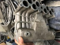
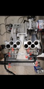
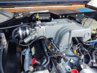
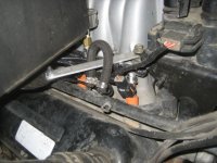
So I have attached a picture of my upper intake and have labeled everything 1-8. I'd love it if the gurus can help me identify what they were all intended for before I start plugging them?
1.) PCV #1 - runs into a F-type tubing system. This is mated with #5. BroncoBowsher had a really good explanation on how the PCV 'plumbing' works a few years ago:
The PCV on the bottom is actually a neat piece of engineering. There are 2 fitting (front and rear) at the very bottom of the intake. The lines Tee together before going into the PCV. This was all done with a purpose. If you get any fluid into the intake (blowby, water splashed in) it can settle at the bottom of the plenum. When the engine is shut off gravity will drain it down and dump it into the crankcase via the PCV. Look at the lines as built by the factory and they have a downward slope to them.
This was done for a reason, and I have seen it happen on other engines. If the liquid accumulates enough it can start to pour into the rear most cylinder. Better to have the oil drain back into the crankcase. Even a little water is no big deal in the crankcase (heat will vaporize it). The one I know really killed an engine was a hard run and the second stage of the intake opened, running a slug of fluid into the cylinder at speed.
Ford engineered a drain for a reason, I made sure to keep it.
https://classicbroncos.com/forums/showpost.php?p=3138415&postcount=11
My question is.. why not simply retain both ports for PCV and use the Explorer tubing system? Why are most folks only leaving 1 port for PCV?
2.) Brake booster. Unless you're running Hydroboost, you'll probably want to keep this
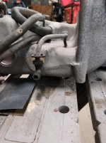
3.) Fuel Pulse Dampener (FPD) - looks like most folks refer to this as a Fuel Pressure Regulator. I plan to keep this, but need to figure out how to plug the extra port that goes to the EGR that was shared with? (see pic) Once again, BroncoBowsher had an excellent explanation on what this is for a few years back:
The retrunless also adds a pulse damper to the fuel rail. It is the thing that looks like a fuel pressure regulator but isn't. What it does is act as an accumulater so when an injector fires the whole mass of the fuel in the fuel line doesn't have to start moving. Also when the injector stops it acts as a bumper so the fuel pressure doesn't hammer the system.
Why returnless? There is a little cost savings in only running 1 fuel line, also less potential for leaks. But the biggy is emissions. A return style dumps hot fuel back into the tank. That wants to vent as vapor. If you keep the tank cooler it is easier to control evaporative emissions. We did a lot of testing of this stuff back in that time frame.
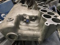
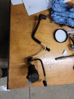
4.) I honestly don't remember what this was for. It has a 90deg plastic fitting at the front (pic attached). Can't find many references to it. Help?
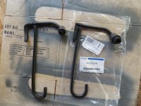
5.) PCV #2 - as mentioned above, I plan to retain this. Although my PCV tubing broke, someone is selling NOS replacements for <$20 on ebay and I have one on the way.
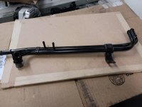
6.) coolant line #1 - I've read that most people cap this off, along with #7 (and run a loop as pictured below). Best I can tell/read, Ford engineered these to flow through the upper intake as sort of a preheat/deicer? My real question is if why abandon this and rather than simply looping the 1/4" on the heating lines, why not just connect them?
7.) coolant line #2 - same as #6
8.) I don't remember what this was used for as well?
I appreciate any feedback y'all might have. Hopefully this consolidated info will help others.
Background:
- 2001 Explorer, reworked EFIGuy harness, using AWD 4R70W
- deleted EGR, Evap
- no Hydroboost
So most of the threads i've read suggest capping all but 3 vacuum ports:
1.) Positive Crankcase Ventilation. However, the explorer actually uses two ports. I'd like to learn more why?
2.) Fuel Pulse Damper (FPD), sometimes referred to as a Fuel Pressure Regulator
3.) Brake booster
So I have attached a picture of my upper intake and have labeled everything 1-8. I'd love it if the gurus can help me identify what they were all intended for before I start plugging them?
1.) PCV #1 - runs into a F-type tubing system. This is mated with #5. BroncoBowsher had a really good explanation on how the PCV 'plumbing' works a few years ago:
The PCV on the bottom is actually a neat piece of engineering. There are 2 fitting (front and rear) at the very bottom of the intake. The lines Tee together before going into the PCV. This was all done with a purpose. If you get any fluid into the intake (blowby, water splashed in) it can settle at the bottom of the plenum. When the engine is shut off gravity will drain it down and dump it into the crankcase via the PCV. Look at the lines as built by the factory and they have a downward slope to them.
This was done for a reason, and I have seen it happen on other engines. If the liquid accumulates enough it can start to pour into the rear most cylinder. Better to have the oil drain back into the crankcase. Even a little water is no big deal in the crankcase (heat will vaporize it). The one I know really killed an engine was a hard run and the second stage of the intake opened, running a slug of fluid into the cylinder at speed.
Ford engineered a drain for a reason, I made sure to keep it.
https://classicbroncos.com/forums/showpost.php?p=3138415&postcount=11
My question is.. why not simply retain both ports for PCV and use the Explorer tubing system? Why are most folks only leaving 1 port for PCV?
2.) Brake booster. Unless you're running Hydroboost, you'll probably want to keep this
3.) Fuel Pulse Dampener (FPD) - looks like most folks refer to this as a Fuel Pressure Regulator. I plan to keep this, but need to figure out how to plug the extra port that goes to the EGR that was shared with? (see pic) Once again, BroncoBowsher had an excellent explanation on what this is for a few years back:
The retrunless also adds a pulse damper to the fuel rail. It is the thing that looks like a fuel pressure regulator but isn't. What it does is act as an accumulater so when an injector fires the whole mass of the fuel in the fuel line doesn't have to start moving. Also when the injector stops it acts as a bumper so the fuel pressure doesn't hammer the system.
Why returnless? There is a little cost savings in only running 1 fuel line, also less potential for leaks. But the biggy is emissions. A return style dumps hot fuel back into the tank. That wants to vent as vapor. If you keep the tank cooler it is easier to control evaporative emissions. We did a lot of testing of this stuff back in that time frame.
4.) I honestly don't remember what this was for. It has a 90deg plastic fitting at the front (pic attached). Can't find many references to it. Help?
5.) PCV #2 - as mentioned above, I plan to retain this. Although my PCV tubing broke, someone is selling NOS replacements for <$20 on ebay and I have one on the way.
6.) coolant line #1 - I've read that most people cap this off, along with #7 (and run a loop as pictured below). Best I can tell/read, Ford engineered these to flow through the upper intake as sort of a preheat/deicer? My real question is if why abandon this and rather than simply looping the 1/4" on the heating lines, why not just connect them?
7.) coolant line #2 - same as #6
8.) I don't remember what this was used for as well?
I appreciate any feedback y'all might have. Hopefully this consolidated info will help others.
Attachments

Last edited: