











Then I slid the drivers radius arm close to the frame hole and saw I was about an inch off.
I placed a floor jack under the drivers radius arm close to the end and applied force until the end of the radius arm was equal with the mounting hole. At this point the axle on the drivers side was about 1 inch off the jack stand. Then I loosened the C cap bolts until I could see the axle shift in the bushings. I had to use a hammer and screw driver to pop the cap from the radius arm. At this point the axle settled and touched the jack stand.
Then I carefully retightened the C cap bolts make it sure the arm didn’t move. I could see the axle remain in the same position on the jack stands so I knew the radius arm was not moving from the location relative to the frame hole. Once all was tight, I torqued both the drivers side and passenger side C cap bolts to 90 lbs.
Others do it differently by leaving the radius arms on the floor but this worked for me.
Next I installed the radius arms into both frame holes.
Place the front bushing and washer on the radius arms.
I used a ratchet strap attached to the front axle and rear leaf spring shackle. Then I aligned the radius arms with the hole and tightened the ratchet strap. The radius arm was pulled into the frame hole enough for me to place the rear bushing, washer and bolt into place and hold it into the frame hole.
Repeat for the opposite side. This is where having the axle on jack stands and rolling foundations make the job easy.
Tighten the bolts but only enough to hold the radius arm into the frame holes.
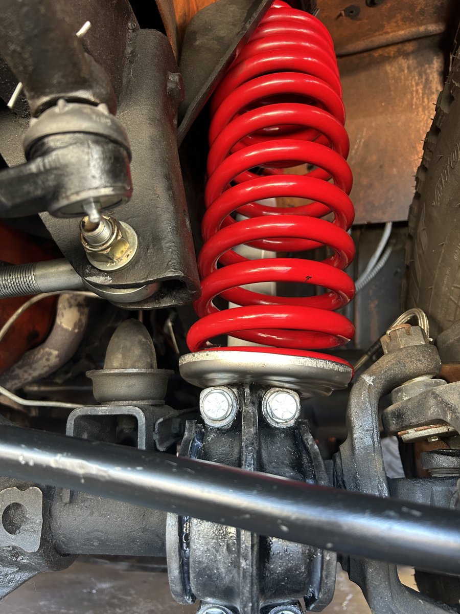
Install the springs.
Install the shocks.
Install the drive shaft.
Remove the axle rolling foundations so that the jack stands under the axle are sitting firmly on the ground
Remove the frame jack stands so that the weight of the vehicle is sitting on the axle and the axel is on the jack stands.
Torque the radius arm at the frame bolts. I torqued the degreed rubber bushings to 90ftlbs.
Recheck the torque on the C caps. Should be about 90 lbs.
Check to ensure axle is centered under the frame. To do this I attached a magnetic plumb line tool to the frame, and marked it on the ground with a piece of tape. Then I attached the plumb line to the axle where it meets the steering knuckle and marked that on the ground with a piece of tape.
Repeat the same procedure on the opposite side of the Bronco using the SAME relative locations to place your plumb line.
I then measured the distances between the frame and axle point on each side. Ensure they are equal measurements. If they are you know your axle is centered. I did this because as I mentioned many years ago I installed a 2.5 inch lift but used the stock track bar. Theoretically this would mean the axle was pulled toward the drivers side. I corrected this by installing an adjustable track bar once I knew the axle was centered.
Once axle is centered, install your track bar.
If you find the axle is not centered, you can use a ratchet strap attached to the axle and frame to pull the axle the direction desired.
Install tie rods.
I had to replace my tied rods. So I did it like this.
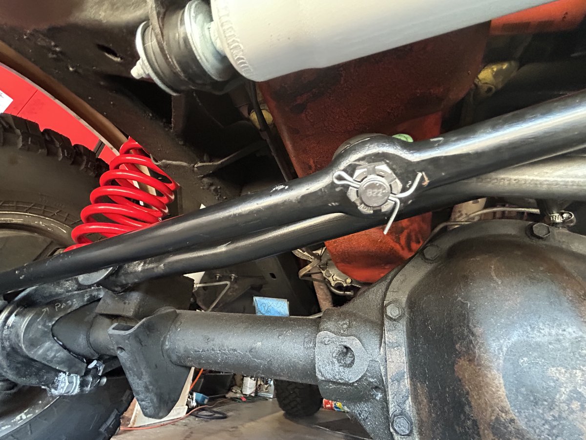
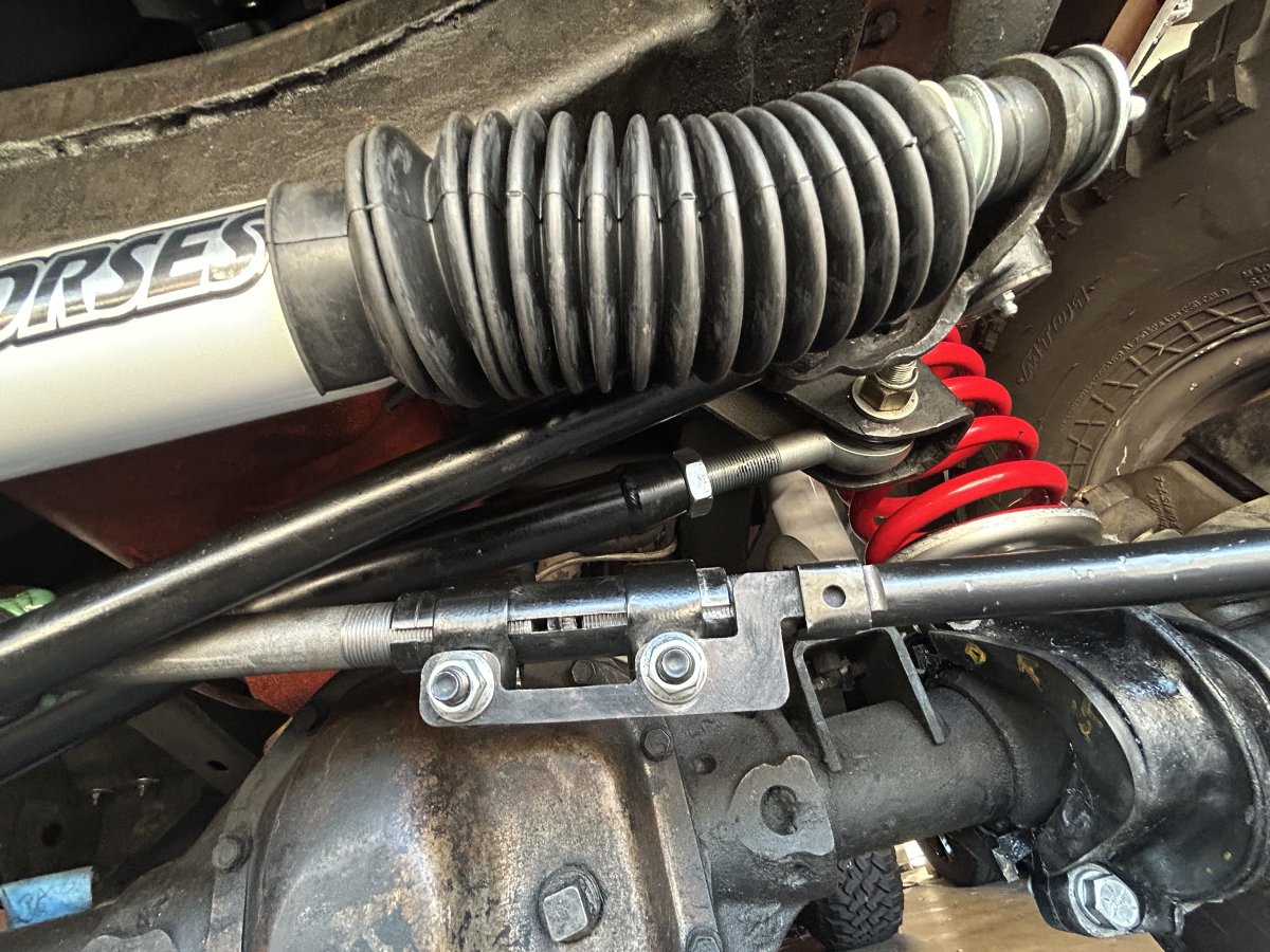
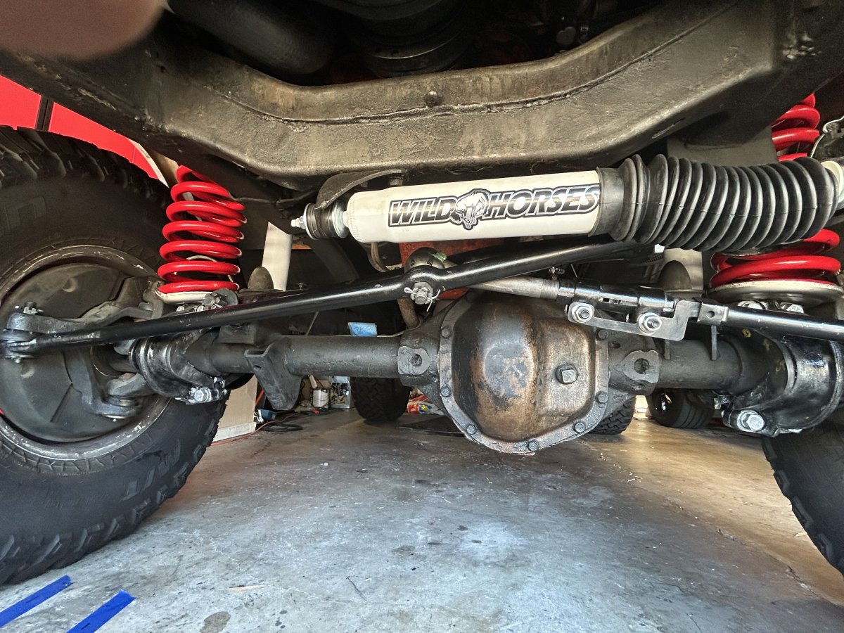
The 1977 came with the inverted Y tied rod. Where the drag link goes from the pitman arm to the passenger side steering knuckle. Then an adjustable tie rod goes from the drag link to the drivers side steering knuckle. I took a measurement from the old tie rod and made sure the new tie rod was the same length as a starting point.
I also measured the distances between from the steering knuckle where the drag link attaches to the drivers knuckle and where the tie rod is attached to the drivers knuckle. I measured center of the tie rod bolt on passenger side to center of the tie rod bolt on the drivers side. It came to 50 inches.
I then installed the drag link into the pitman arm and the passengers side knuckle.
Then installed the tie rod to the drag link and then to the drivers steering knuckle.
I had to shorten up the tie rod using the adjusting sleeve before I could place the tie rod bolt into the steering knuckle on the drivers side.
Next I had to measure to make sure the wheels were in the correct orientation.
I purchased some of the alignment tools that attach to the wheel studs.
Attach one alignment tool to the drivers side using the lug nuts. Use a level to ensure the alignment tool was level.
Repeat for the passenger side.
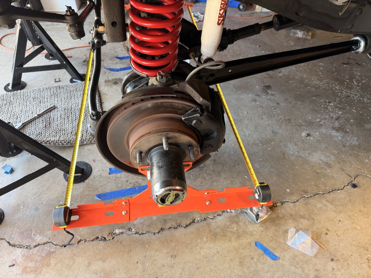
Run the included tape measures at the front of the drivers and passenger alignment tool and the other tape measure at the rear of the alignment tools.
I found that the measurements showed a toe out of about one inch. Which was way off.
The Bronco needs a toe in of about 1/8 to 1/4 inch.
I adjusted the tie rod (reduced) until the toe in was 1/4 inch.
Then tightened the tie rod adjusting sleeve bolts so the adjuster does not move.
I realize this wasn’t as accurate as an alignment shop but I just wanted to get it close.
Reinstall the steering stabilizer
Recheck all torques
Install the wheels and check for lean.
After doing all this I drove the Bronco. The steering was tight and it was tracking straight with no steering input. It felt like the truck was new.
This is how I did this project. Others may have different procedures but wanted to share what worked for me.
GOOD LUCK.
I placed a floor jack under the drivers radius arm close to the end and applied force until the end of the radius arm was equal with the mounting hole. At this point the axle on the drivers side was about 1 inch off the jack stand. Then I loosened the C cap bolts until I could see the axle shift in the bushings. I had to use a hammer and screw driver to pop the cap from the radius arm. At this point the axle settled and touched the jack stand.
Then I carefully retightened the C cap bolts make it sure the arm didn’t move. I could see the axle remain in the same position on the jack stands so I knew the radius arm was not moving from the location relative to the frame hole. Once all was tight, I torqued both the drivers side and passenger side C cap bolts to 90 lbs.
Others do it differently by leaving the radius arms on the floor but this worked for me.
Next I installed the radius arms into both frame holes.
Place the front bushing and washer on the radius arms.
I used a ratchet strap attached to the front axle and rear leaf spring shackle. Then I aligned the radius arms with the hole and tightened the ratchet strap. The radius arm was pulled into the frame hole enough for me to place the rear bushing, washer and bolt into place and hold it into the frame hole.
Repeat for the opposite side. This is where having the axle on jack stands and rolling foundations make the job easy.
Tighten the bolts but only enough to hold the radius arm into the frame holes.
Install the springs.
Install the shocks.
Install the drive shaft.
Remove the axle rolling foundations so that the jack stands under the axle are sitting firmly on the ground
Remove the frame jack stands so that the weight of the vehicle is sitting on the axle and the axel is on the jack stands.
Torque the radius arm at the frame bolts. I torqued the degreed rubber bushings to 90ftlbs.
Recheck the torque on the C caps. Should be about 90 lbs.
Check to ensure axle is centered under the frame. To do this I attached a magnetic plumb line tool to the frame, and marked it on the ground with a piece of tape. Then I attached the plumb line to the axle where it meets the steering knuckle and marked that on the ground with a piece of tape.
Repeat the same procedure on the opposite side of the Bronco using the SAME relative locations to place your plumb line.
I then measured the distances between the frame and axle point on each side. Ensure they are equal measurements. If they are you know your axle is centered. I did this because as I mentioned many years ago I installed a 2.5 inch lift but used the stock track bar. Theoretically this would mean the axle was pulled toward the drivers side. I corrected this by installing an adjustable track bar once I knew the axle was centered.
Once axle is centered, install your track bar.
If you find the axle is not centered, you can use a ratchet strap attached to the axle and frame to pull the axle the direction desired.
Install tie rods.
I had to replace my tied rods. So I did it like this.
The 1977 came with the inverted Y tied rod. Where the drag link goes from the pitman arm to the passenger side steering knuckle. Then an adjustable tie rod goes from the drag link to the drivers side steering knuckle. I took a measurement from the old tie rod and made sure the new tie rod was the same length as a starting point.
I also measured the distances between from the steering knuckle where the drag link attaches to the drivers knuckle and where the tie rod is attached to the drivers knuckle. I measured center of the tie rod bolt on passenger side to center of the tie rod bolt on the drivers side. It came to 50 inches.
I then installed the drag link into the pitman arm and the passengers side knuckle.
Then installed the tie rod to the drag link and then to the drivers steering knuckle.
I had to shorten up the tie rod using the adjusting sleeve before I could place the tie rod bolt into the steering knuckle on the drivers side.
Next I had to measure to make sure the wheels were in the correct orientation.
I purchased some of the alignment tools that attach to the wheel studs.
Attach one alignment tool to the drivers side using the lug nuts. Use a level to ensure the alignment tool was level.
Repeat for the passenger side.
Run the included tape measures at the front of the drivers and passenger alignment tool and the other tape measure at the rear of the alignment tools.
I found that the measurements showed a toe out of about one inch. Which was way off.
The Bronco needs a toe in of about 1/8 to 1/4 inch.
I adjusted the tie rod (reduced) until the toe in was 1/4 inch.
Then tightened the tie rod adjusting sleeve bolts so the adjuster does not move.
I realize this wasn’t as accurate as an alignment shop but I just wanted to get it close.
Reinstall the steering stabilizer
Recheck all torques
Install the wheels and check for lean.
After doing all this I drove the Bronco. The steering was tight and it was tracking straight with no steering input. It felt like the truck was new.
This is how I did this project. Others may have different procedures but wanted to share what worked for me.
GOOD LUCK.
Last edited:


