Steve's got your best advice for the stock alternator probably. Just leave it (with the new sections of course) and go from there.
You often see 60, 70 and even 80 amp Maxi-Fuses (physically smaller than a Mega-Fuse) used in the aftermarket harnesses instead of fusible links, but it's typically with a different setup for the charge circuit as well.
It's just protecting the power circuit on a much shorter length (about half the normal length) that feeds the fuse panel. This shorter section of 10ga wire can handle a lot more amperage than the stock one of the same gauge can. Partly for being new, but mostly for just being shorter.
So in Steve's scenario, they can handle the 80a where the stock one might not.
In those harnesses the charging duties are handled directly over an even shorter wire from the alternator directly to the starter relay/battery connection.
But to add to the discussion, both Painless and Centech offer their harnesses with "stock-ish" layouts where the alternator's charge wire runs the full length with the same 10ga size.
Where Painless uses a 60a Maxi-Fuse (I believe they've recently up-sized that to at least 70 now though?) in lieu of a fusible link, but Centech keeps the fusible link in their design.
Not sure about the routing of the Painless charge wire, but the Centech charge wire may actually be effectively shorter than stock because it goes to a junction on the back of the fuse panel, and from there goes on it's rounds.
I'm not sure if that makes any difference in load handling ability, so maybe Steve can say if that changes things at all?
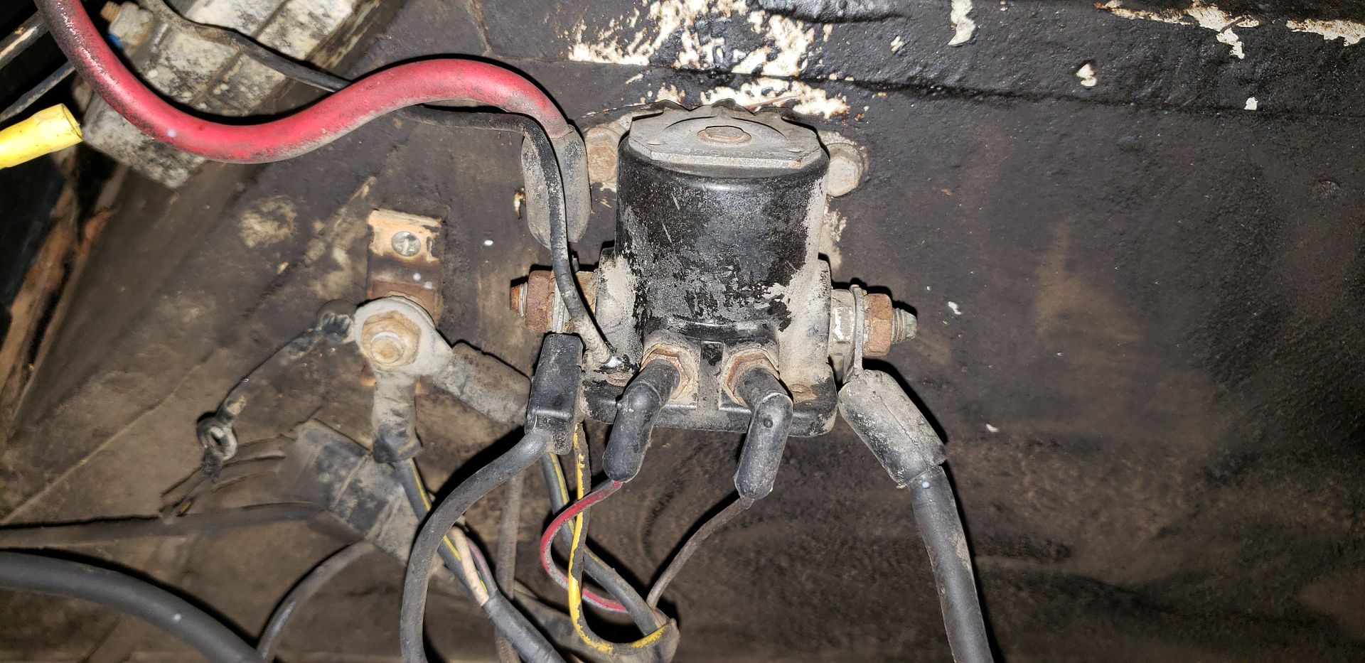
Where instead of one long 10ga wire from alternator, through the cab and back to the battery, there is a shorter section terminated at a terminal stud.
In other words my question being, in theory are three separate 4' sections of 10ga wire run in series any more or less susceptible to overloading than one long 12' wire is?
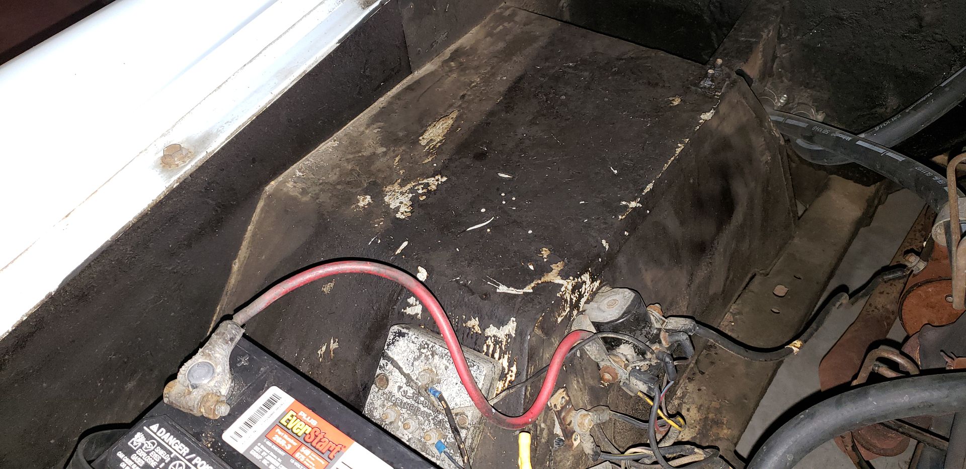
I cut the blk/yellow charge wire and extended it w/ a red one to the alt. It is just taped back into the bundle specifically to tidy up for the picture.
What are you going to be doing with that section of Black w/yellow wire that's exposed right now? Need to cap it off safely somehow.
My current alt has the three wires and I added a 4th wire from the stator directly to the electric choke on the edelbrock.
Stator output is not 12v as far as I know, so your aftermarket 12v choke coil may not work properly. Either not opening as quickly as it should, or perhaps not opening all the way at all?
I would guess it would eventually open, just at a slower rate.
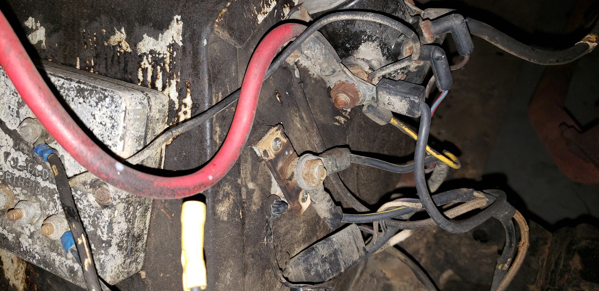
I too was wondering if that molded "strain relief" was something to do with a fuse...
I guess Steve has set me straight. The reason I thought it might be the actual fusible link section was due in part at least to that piece getting "puffy and soft" when the fusible link has blown.
Over the years many have reported blown factory fusible links that did not melt the wire or leave any visible burn marks other than the half-melted strain relief at the very end.
It does make sense though, that the first whole section of that wire would be the link wire. Most EB's had a 3-wire connector several inches up the harness. So if you had a melt-down it was not the entire wire that needed to be replaced.
If your '66 does not have that plug/connector, not sure how they did it. In that case we're back to wondering how the '66's were wired.
I think Steve was checking out Viper's data and had plans to eventually create a '66 specific diagram to go along with all of his others.
Hope that comes to fruition someday.
Paul


")