


OP
OP
Cooter_76
Sr. Member
- Joined
- May 18, 2004
- Messages
- 863
Cooter I’m install the same 2 into 1 exhaust with headers as you. I’m running into the same problem as you with the transmission lines on the 4r70w. But my question is how did u get the transmission dipstick tube to clear the header? My in hits and won’t allow me to install my header. Also do you think the heat from the headers will be problem on the transmission lines running across the top of the frame rail? I ask because I installed my in the same way.
Sent from my iPhone using Tapatalk
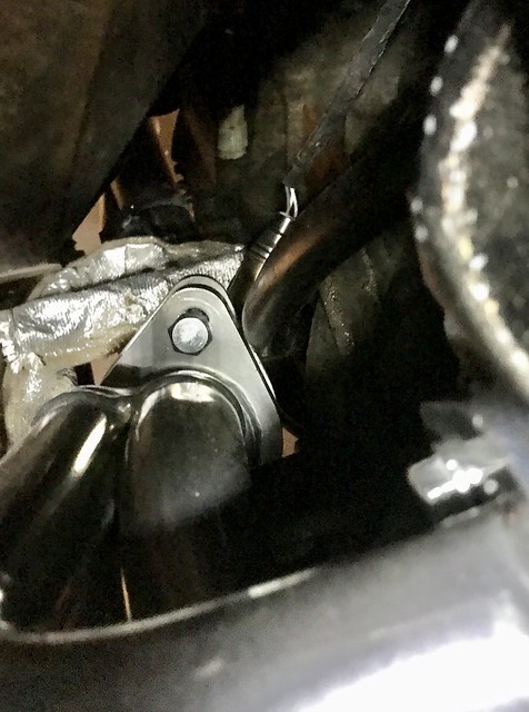
My dipstick tube is making contact with the header flange. I don't remember if I had to bend the tube to get it to fit, but I know I've since been able to pull the tube and reinstall without messing with the headers.
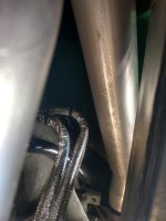
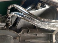
I sure hope the transmission lines won't see too much heat from the headers. I tried to run them as far away as I could. I also put some heat sleeve on the lines where they cross over the exhaust.

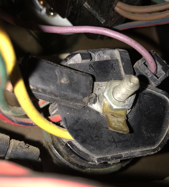
 But it's the perfect place to mount the negative cable.