• Welcome to ClassicBroncos! - You are currently viewing the forums as a GUEST. To take advantage of all the site features, please take a moment to register. It's fast, simple and absolutely free. So please join our community today!
    If you have problems registering or can't log into your account, please contact Admin.

Electrical help

ntsqd

heratic car camper
Joined
Jan 30, 2005
Messages
5,952
Loc.
Upper SoKA
The MSEE's that I worked with at gigavac both stressed that the contact force was more important to conductivity than was the area of the contact. When we've been conditioned to think that cross-sectional area = ampacity this is a mentally difficult shifting of gears. One of them grabbed me one day and showed me a prototype failure that clearly demonstrated this. I believe it, even if I don't fully understand it.
 

Steve83

Bronco Guru
Joined
Jul 16, 2003
Messages
9,359
Loc.
Memphis, TN, USA, Earth, Milky Way
As an engineer who designed sub-sea submersible electrical connectors, putting dielectric grease on the contacts...
As an engineer who designs electrical connectors, I'd expect you to differentiate between "contacts" which are used in switches & relays, vs. "terminals" which are used in connectors.

But then, I'd also expect such an engineer to realize that all submersible artifacts are sub-sea, and vice versa. It's tautologically redundant.
If the contacts are doing their job correctly they 'wipe' any oxidation on the mating surfaces off when the contacts are slid together.
If the connectors get slid apart & back together frequently (relative to their environment & purpose), then that would certainly be true. But since the topic was a fan relay that can be expected to remain plugged in for decades, I don't think that's applicable.
...any dielectric grease will have been removed from between the actual surfaces in contact...
If dielectric grease were ONLY grease, then that would probably be true enough. But it's not. It contains sand (glass beads) to aid in maintaining the dielectric potential between (for example) a heat sink & a circuit that might require a heat sink, but that would be adversely affected by any RFI or other induced eddy currents in the metal sink. So the sand maintains that gap mechanically that might otherwise be lost if pure grease was used. That's why a grease labelled & marketed (and, one would hope, engineered by an engineer who designs greases) as a dielectric should never be used where electrical contact of any kind is desirable. Or do you think you're the only engineer who takes his work seriously?
Unlike dielectric grease, oxidation can work it's way into the mating surfaces if unprotected.
IDK what you think protects the mating surfaces from dielectric grease working its way in, but grease does creep over time. We've all seen it - even those of us who are not sub-sea submersible engineers. So it certainly happens when the grease that has been wiped a few microns away is allowed to creep back in over a few months or decades of continuous connection.
Contrary to at least one person's opinion, Ford engineers are not God and do not know it all or are infallible.
Contrary to at least one person's opinion, neither are sub-sea submersible engineers.
There's attempting to understand the design intent, and then there's kneeling in supplication while facing towards Dearborn.
You're omitting at least one other likely possibility: there's also actual understanding of the design intent (regardless of where that designer worked), based at least in part on reading the MSDS for the chemical in question.
...too much grease...then becomes the conductor itself.
No, as I said initially: electrical grease is not conductive. It's actually silicone grease very similar to that used in dielectric grease, but with properties sufficiently distinct to make it particularly suited to maintaining electrical terminal conductivity, instead of preventing it like grease engineered as dielectric does. It's vaguely comparable to a steel sword and a steel scalpel; they're made of the same material & both have sharp edges for cutting flesh - but one is for killing, and one is for saving life. As similar as they might appear to someone not familiar with them, neither would be particularly good at doing the other's job.

...like dielectric grease not doing the job that electrical grease is made to do.
...friction connection (again, if that’s a proper term?)
I think "terminal contact force" might be what you mean, since I think you're talking about the normal (perpendicularl to the surfaces) force that holds the 2 conductors in-contact, allowing current to flow between them. Friction would be a tangential force (parallel to the surfaces) that resists them sliding against each other.
...to render the connection inoperable.
That's not the issue. The connection is likely to remain operable to some degree. But it won't be as good as if the correct material was used. Sort of like a surgeon trying to use a sword to save the life of someone who took a scalpel to a swordfight. Yeah, he might get the job done, and the patient might even survive for years. But it won't be as pretty as if he had used the right tool.
...the grease is simply to seal the metal connections from air and moisture, that what other wise result in long term oxidation.
It'll never seal out air or Oxygen. But it's exceptionally good at repelling water, which often contains salts that become acidic or caustic to refined metals. Even the CO2 in most water (even tiny droplets too small to be seen) creates a weak acid. That's the grease's primary function, even sub-sea. Making the plastic connector shells slide together & apart more-easily is just a side-effect.
...just like Steve83 wrote, I use conductive grease...
I've never owned, used, or advocated conductive grease anywhere. The grease I apply to alternators & their brackets is non-conductive silicone-based electrical grease marketed by Ford for that purpose. Just like in connectors; its function is to slow the corrosion of the metals in-contact (the Aluminum castings) by repelling water. Nothing else.
Ford lists the XG-12 electrical grease as conductive...
Where? Not on this page, nor on the linked MSDS:
I would be inclined to only use it where a silicon grease is undesirable for some reason.
XG-12 is a silicone grease.
... I've worked on thousands ii'd say inconclusive
How many do you think Ford engineers studied, tested, & analyzed during their development of XG-12 before coming to a conclusion? Have you ever seen an original 2G alternator (built & installed before XG-12 was developed) catch fire? I have - firsthand. ;) At least twice that I specifically remember - it was exciting both times.
GM exterior lighting used greased sockets plenty of issues there...
That's just one of many reasons that I don't buy or enjoy GM vehicles - I think their engineering is noticeably inferior to Ford's in many ways beyond grease on electrical terminals.
...the contact force was more important to conductivity than was the area of the contact. ... I believe it, even if I don't fully understand it.
Not having seen it, my guess would be that (assuming the force can be maintained as the points of contact deform) the heat of an insufficient area's resistance would melt those points until they became large enough to carry the current below the metals' melting points. And if different metals were used, that would prevent fusing (ERW), allowing the contact to be broken later. But that's just a blind guess.

 
Last edited:
OP
OP
Bitch'nBronco

Bitch'nBronco

Contributor
Loose Cannon
Joined
Dec 1, 2005
Messages
3,616
Loc.
Ringwood, NJ
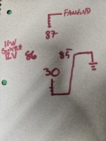
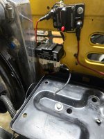
Finally getting around to changing the wiring to match @Steve83 diagram. My question, is can I use a relay as a switched ground? Meaning, the relay gets switched power from the ignition to complete the ground for the fan? I dont want the fan to run when the ignition is turned off, and was trying to think of ways (without adding an additional swtich in the cab) to turn the fan off when the engine is off. Sorry if im dense, just want to make this reliable without draining the battery.
 

Attachments

  • 20260419_141514.jpg
    20260419_141514.jpg
    226.1 KB · Views: 117
  • 20260419_141920.jpg
    20260419_141920.jpg
    190.2 KB · Views: 103

Steve83

Bronco Guru
Joined
Jul 16, 2003
Messages
9,359
Loc.
Memphis, TN, USA, Earth, Milky Way
Finally getting around to changing the wiring to match @Steve83 diagram.
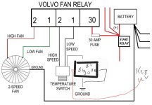
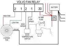
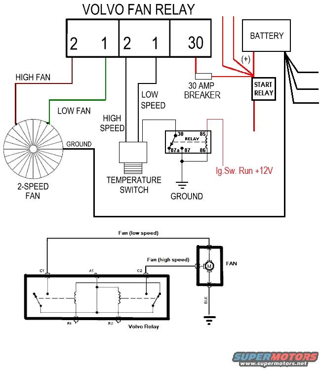
If you mean you're changing to this configuration:
cbfanrelays.jpg

...then I don't understand this:
...I dont have a toggle switch. Im using the ignition switch in its place.
The ig.sw. doesn't have a terminal that's grounded in RUN. If you wired the temp.sw. ground wire to the ig.sw. P terminal with the Pu/Wh wire, then the fan would only work with the key in the START position, so I need more detail to understand how you had it working, and how best to add the functionality that you want. Pics of your ig.sw. wiring would be good. But your 2nd pic in your last post shows you have a 30A breaker where your diagram indicates a 30A fuse, which is another fact worth noting.
...can I use a relay as a switched ground? Meaning, the relay gets switched power from the ignition to complete the ground for the fan?
You could, but it would be pointless & you'd have the same problem as before: the relay terminals would overheat. You already have the Volvo relay that turns the fan on & off, so adding another relay on another high-current fan wire would only add complexity & failure points. The fan return wire needs to be as UNinterrupted as possible going back to the B- post, like the starter return (block ground) or a winch return wire (any high-current load).
I dont want the fan to run when the ignition is turned off, and was trying to think of ways (without adding an additional swtich in the cab) to turn the fan off when the engine is off. Sorry if im dense, just want to make this reliable without draining the battery.
If the toggle in the diagram is actually the ig.sw., then the ig.sw. already kills the fan by killing the input to the Volvo relay through the temp.sw. There's no benefit to adding a 2nd kill, unless you think the Volvo relay is likely to weld its terminals shut (on). And in that case, the best fix would be to replace it with a better relay that won't (like a solid-state or Mercury relay, or just a relay rated for a lot more current than the fan can ever draw).

You should put ALL your Bronco's details & history (as much as you know) into your signature(<-click that) so it shows with each post, as this page explains:

(click this text)


Phone apps don't always show signatures, so you may need to switch to a real browser in desktop mode on your phone, or just use a desktop/laptop computer. The more pics you post (NOT in your sig) of the truck, engine, wiring, labels, & undercarriage, the more likely we can help you.
 

ntsqd

heratic car camper
Joined
Jan 30, 2005
Messages
5,952
Loc.
Upper SoKA
I've done so on multiple occasions. It is actually my preferred way to run a relay and is how most ECU's/PCM's control them.

FWTIW: My '84 Rabbit diesel Caddy ('truck') was built so that the coolant fan ran anytime that the t-stat said so. On, running, or not if the coolant was hot enough the fan ran. I see an advantage in doing it that way. You don't get that temperature spike thru the coolant system right after a hot shut-down. Those that let the engine idle for a few minutes after arriving may never have seen this. I didn't see it very often, but once in a while the situation required an immediate hot shut-down. My first electric fan was on the Ranchero about '92 or '93. I wired it key-on to run, but then had a manual over-ride that would run the fan regardless.
 
OP
OP
Bitch'nBronco

Bitch'nBronco

Contributor
Loose Cannon
Joined
Dec 1, 2005
Messages
3,616
Loc.
Ringwood, NJ
If you mean you're changing to this configuration:
cbfanrelays.jpg

...then I don't understand this:

The ig.sw. doesn't have a terminal that's grounded in RUN. If you wired the temp.sw. ground wire to the ig.sw. P terminal with the Pu/Wh wire, then the fan would only work with the key in the START position, so I need more detail to understand how you had it working, and how best to add the functionality that you want. Pics of your ig.sw. wiring would be good. But your 2nd pic in your last post shows you have a 30A breaker where your diagram indicates a 30A fuse, which is another fact worth noting.

You could, but it would be pointless & you'd have the same problem as before: the relay terminals would overheat. You already have the Volvo relay that turns the fan on & off, so adding another relay on another high-current fan wire would only add complexity & failure points. The fan return wire needs to be as UNinterrupted as possible going back to the B- post, like the starter return (block ground) or a winch return wire (any high-current load).

If the toggle in the diagram is actually the ig.sw., then the ig.sw. already kills the fan by killing the input to the Volvo relay through the temp.sw. There's no benefit to adding a 2nd kill, unless you think the Volvo relay is likely to weld its terminals shut (on). And in that case, the best fix would be to replace it with a better relay that won't (like a solid-state or Mercury relay, or just a relay rated for a lot more current than the fan can ever draw).

You should put ALL your Bronco's details & history (as much as you know) into your signature(<-click that) so it shows with each post, as this page explains:

(click this text)


Phone apps don't always show signatures, so you may need to switch to a real browser in desktop mode on your phone, or just use a desktop/laptop computer. The more pics you post (NOT in your sig) of the truck, engine, wiring, labels, & undercarriage, the more likely we can help you.
Yes, I'm wiring the fans to reflect the first photo in your reply

I should have been more specific. My Bronco is wired with an aftermarket 21 fuse universal harness.

Previously, the relay I used before the volvo relay was activated using 12v from the power antenna circuit. It only gets 12v when the key is in the run position. Instead of ignition switch, I should have said 12v keyed power.

From your diagram, instead of an actual switch to interrupt the ground on the thermal switch, I was going to use the relay as the switch. I'll try and draw a diagram to show what I mean better.

In reference to your point about the Temp signal wire, are you saying I could I run the ground from the thermal switch negative post to the temp sender and it would prevent the thermal switch from triggering the fan when the ignition key is off?

I modified the diagrams to try to show what I'm trying to achieve. The first diagram is using the relay and the second one is what I interpreted from your comment about temp signal wire. My temp sender is from Marshall Gauges and has 2 wires. One to the signal wire and a second that I've grounded to the block. If I connect my thermal switch ground to the temp sender wire, will it interfere with the gage reading? From what I understand, the signal is sort of like a resistance reading, correlated to temperature. I like this option if it doesn't mess with my engine temp reading.
 

Attachments

  • cbfanrelays(1).jpg
    cbfanrelays(1).jpg
    68.9 KB · Views: 96
  • cbfanrelays(2).jpg
    cbfanrelays(2).jpg
    63.6 KB · Views: 97

Steve83

Bronco Guru
Joined
Jul 16, 2003
Messages
9,359
Loc.
Memphis, TN, USA, Earth, Milky Way
The plot thickens...
Previously, the relay...was activated using 12v from the power antenna circuit. It only gets 12v when the key is in the run position.
OK, I see why I was confused. Your original diagram showed a toggle switch, so I re-drew it (almost a year ago) with the toggle in the ground for the temperature switch. But since the toggle is actually the ig.sw., it won't work that way.
...are you saying I could I run the ground from the thermal switch negative post to the temp sender...
No, I didn't say anything about the (gauge) temperature sender. I was only talking about the temp.sw. for the Volvo relay.

Yes, your first drawing should work, using the ig.sw. +12V output to control a small relay that breaks the low-current ground for the temperature switch (not the high-current fan motor).

cbfanrelays.jpg
 
Last edited:
OP
OP
Bitch'nBronco

Bitch'nBronco

Contributor
Loose Cannon
Joined
Dec 1, 2005
Messages
3,616
Loc.
Ringwood, NJ
I finished wiring it, fan runs great. Maybe I'm imagining it, but it seems like the high speed fan is pulling a lot harder than it did before. I also swapped in a new battery so that may be contributing to it
 
Last edited:
Top