• Welcome to ClassicBroncos! - You are currently viewing the forums as a GUEST. To take advantage of all the site features, please take a moment to register. It's fast, simple and absolutely free. So please join our community today!
    If you have problems registering or can't log into your account, please contact Admin.

Electrical Issue - No Power to Dash

Jambi

Contributor
Jr. Member
Joined
Aug 3, 2012
Messages
115
I did a bonehead thing that ended up melting the ground wires to my radio and the heater and now I have no power to the dash. I've been doing a lot of reading on the forums and I think my culprit might be the fusible link going from the starter solenoid. Based on how it's been described in the posts I've read, I'm unclear if what I'm looking at is the fusible link so I just wanted to find out for sure. Is this the fusible link?
 

Attachments

  • 10g_Wire.jpg
    10g_Wire.jpg
    20 KB · Views: 15
Last edited:

DirtDonk

Contributor
Bronco Guru
Joined
Nov 3, 2003
Messages
49,025
Yes, that should be your main fusible link.
Is that yellow wire molded into it as well? Is that for the voltage regulator, or the horn relay?
I assume the voltage regulator, but I’ve never seen a double molded one on a Bronco like that. Seen them on other vehicles, but I can’t remember ever seeing them on Broncos.

Got a picture of it from the other side? Doesn’t look puffy or melted from here, but they are often hard to tell.
What year is the Bronco?

To be certain here, do you have no power to anything including headlights, horn, and brake lights?
 
OP
OP
Jambi

Jambi

Contributor
Jr. Member
Joined
Aug 3, 2012
Messages
115
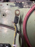
My Bronco is a 69. Yes, the yellow wire is molded into it as well. The yellow wire went to the voltage regulator, which I don't have anymore because I upgraded to EFI and the 4g alternator several years ago. I've read that yellow wire is no longer needed with the EFI/4g, but because of how it's molded in with the black wire, I cut it, put a wire nut on the end and left it. Not sure if that was the right thing to do, but that's what I did. What I'm not understanding is when I take the wire nut off the yellow wire and test for continuity and voltage (not sure if I need to test for both, but I did) I get both. If the fusible link was in fact affected, wouldn't I get nothing for continuity and voltage?

To answer your last question: correct, I have no power to anything at the dash including headlights, brake lights, etc. Also, when probing the center threaded stud on the back of the ignition switch shouldn't I be getting continuity and 12v? I get nothing. I also removed the black wire that attaches to that stud (this is the same wire that goes to that fusible link, correct?) and I get no continuity or voltage
 
Last edited:

Oldtimer

Contributor
Jr. Member with Sr. moments
Joined
Feb 4, 2005
Messages
1,169
Loc.
Sunnyvale, CA
The wire connected to stud on ignition switch is to accessories. Black yellow wire from alternator on STOCK Bronco harness feeds power to ignition switch via a splice buried on harness. I think power to ignition switch is on yellow wire after the splice.
 

DirtDonk

Contributor
Bronco Guru
Joined
Nov 3, 2003
Messages
49,025
Yep, the black with green wire on the ignition switch will only have power when the switches turned to ACC or ON.

I’m not sure you should see power on the yellow wire because I have no idea how it’s connected to the fusible link. However, it’s a good bet that with no power there the fusible link is blown.
I don’t really know how to test them unless there is a voltage drop test you can perform.

Being a 69, you have the two rectangular firewall connectors. Disconnect them on the engine compartment side and measure continuity and voltage between the fusible link ring terminal, and the black wire in the connector. Should be easier to test over that shorter distance.
And you could also inspect the connectors and make sure nothing melted inside there.
Shouldn’t be a problem, because that’s what the fusible link is supposed to protect.
 

DirtDonk

Contributor
Bronco Guru
Joined
Nov 3, 2003
Messages
49,025
But speaking of those firewall connectors, pulling them both and inspecting all the connections and wires is a good idea now and then.
Make sure they are clean and rust free. And no silvery white oxidation on the surface that would impede electron flow.
Probably install some proper grease/sealant. I still use dielectric grease, but there are those here that can better explain what the good bad and ugly is of using that particular product. Maybe there is something better for this application.
 

Oldtimer

Contributor
Jr. Member with Sr. moments
Joined
Feb 4, 2005
Messages
1,169
Loc.
Sunnyvale, CA
This and attached PDF may help in tracing your circuits.
Not sure how 4G alternator is connected, and what it changes on these schematics.

1739145542605.png
 

Attachments

  • 68-71ignition.pdf
    551 KB · Views: 10
Top