• Welcome to ClassicBroncos! - You are currently viewing the forums as a GUEST. To take advantage of all the site features, please take a moment to register. It's fast, simple and absolutely free. So please join our community today!
    If you have problems registering or can't log into your account, please contact Admin.

Headlight switch and ignition wiring questions

kaisermusic

Sr. Member
Joined
Aug 30, 2004
Messages
467
Loc.
Chehalis WA
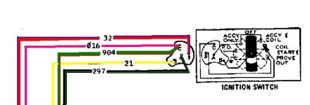
I'm trying to rewire my 67 from scratch using seabiscuits colored diagrams for the 67. When I pulled out my headlight switch I had this:

c8b66693e260c2c0257c92dc2eca7119_zps12c8518d.jpg


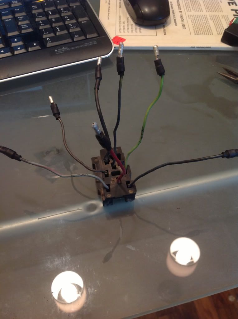
Which doesn't match at all to the wiring diagram. The colors and positions are all different. How do I determine what poles are what? I'm completely lost there.

Also, my ignition only has three wires:

a633558841cb3a3e5c2e0e1c164ff669_zps592399b3.jpg


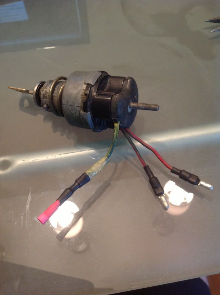
A yellow, and what looks to be one solid red, and one red with a blue stripe?

This also does not match the wiring diagram. Need to know how to hook this up. I think the diagram calls for the voltage regulator to also have a green wire off of the ignition?
 

DirtDonk

Contributor
Bronco Guru
Joined
Nov 3, 2003
Messages
47,941
I'll bring this back to the top for the morning crew.

In the meantime, for the light switch the Black w/orange(?) wire should be the 12v power IN from the battery.
Light Blue w/red should be the dash illumination.
Red should be 12v power OUT to the brake light switch.
Red w/yellow should be out to headlight dimmer switch on the floor. But I don't see that color in your pic, so not sure.
Brown should be power out to the running lights. This would be front and rear only, obviously, since your '67 would not have come with side-marker lights. AND, it's very likely that it's wired so that the front running lamps come on only with the first position and go back out with the second position of the switch.
So are there two Browns? If so, one is to front, one is to rear. They could be combined, but because it's such an early Bronco, it might have two.
I'm not sure what the other one or two are, so maybe Viper of one of the others will chime in with that tidbit. He probably has a nice diagram to show you, so I just wanted to take up some time and put it back to the top.

And like any switch, it can be tested with an ohm-meter too, to determine which wire positions are working with which positions of the switch.

Good luck.

Paul
 

DirtDonk

Contributor
Bronco Guru
Joined
Nov 3, 2003
Messages
47,941
Ignition switch looks like an original! Does it still work?
No side terminal (unless it's hidden on the bottom in the pic?) means you may not have the little red brake warning light on the dash?

Anyway, the center post should have a large Black w/green stripe wire with a molded-on ring terminal held in by a nut. The nut also holds the entire black connector shroud to the switch. Which means that theoretically you should be able to grab the black part by the edges and pull/wiggle/cuss it off the switch body itself.
Inside of it you'll find basically what look like standard push-on blade terminals.

Should be:
1. A Red w/blue wire - Energizes the starter relay and cranks the motor.
2. A Red w/green wire - Positive side of the ignition coil
This wire could also have been Pink coming off the switch, but not always.
3. Green w/red stripe - Powers the voltage regulator and some of the fuses on a common buss-bar in the fuse box. Just the ones that are hot in "RUN" only. Not in "ACC" mode.

Think that's it for now. I'm only guessing at some of that because the '67 might have been slightly different from the ones I'm more used to.
So wait again for second opinions.

And here again, some easy testing with a multi-meter can net you the basic answers of what goes where and when. Switch-wise that is.

Paul
 
OP
OP
K

kaisermusic

Sr. Member
Joined
Aug 30, 2004
Messages
467
Loc.
Chehalis WA
thanks for the reply.

I need a digital multimeter. I used to have a nice sperry but had to give it back to its owner....

On the ignition, I'm not sure if it is original. It has no green wire at all. Thats why I'm stumped as to what connects to the green off my volt reg. There is also no side terminal. So its just the three wires. A yellow, what looks like a solid red which I guess could be pink, and a red with blue stripe.

The headlight switch I am still really lost on. I have seen a bunch of diagrams, but none of them match up to mine. Even if I have some of the colors you listed, if they aren't connected to the right terminals it wouldnt work correctly right? Hopefully someone can make sense of this...
 

Viperwolf1

Contributor
electron whisperer
Joined
Aug 23, 2007
Messages
24,335
Don't get hung up on wire colors. Lot's of things could have happened in the last 4 decades. Look at the pin locations and test with an ohmmeter as Paul said.

Ign switch
pink (or red-green)=12V in RUN, resistor wire to coil +, circuit #16
black-green=12v in RUN and ACC, to gauges, circuit #297
yellow=12V to ign switch, circuit #21
green-red=12V in RUN, to voltage reg, circuit #904
red-blue=12V in START, to starter solenoid, circuit #32
pink-white=GND in START, brake warning lamp, circuit #977
 

Attachments

  • 68headlightswitch.gif
    68headlightswitch.gif
    11.3 KB · Views: 119
  • 68-71ign sw.JPG
    68-71ign sw.JPG
    29.8 KB · Views: 109
OP
OP
K

kaisermusic

Sr. Member
Joined
Aug 30, 2004
Messages
467
Loc.
Chehalis WA
It looks like on the ignition that 016 and 904 are coming off of that same terminal. I have no green/red wire so can I just tag onto the pink line and send it to the volt reg?
 

Viperwolf1

Contributor
electron whisperer
Joined
Aug 23, 2007
Messages
24,335
It looks like on the ignition that 016 and 904 are coming off of that same terminal. I have no green/red wire so can I just tag onto the pink line and send it to the volt reg?

They do go to the same terminal. The pink wire is the ignition resistor wire. Not a good idea to cut it. If you have to do it as close to the switch as possible.
 
OP
OP
K

kaisermusic

Sr. Member
Joined
Aug 30, 2004
Messages
467
Loc.
Chehalis WA
I was thinking of splitting it in the female connector that attaches to the male end I already have in the pic. Hopefully that's ok, otherwise I'm not sure what to do. I want to retain the factory ignition and its odd that there isn't a green wire on there...
 

Viperwolf1

Contributor
electron whisperer
Joined
Aug 23, 2007
Messages
24,335
I was thinking of splitting it in the female connector that attaches to the male end I already have in the pic. Hopefully that's ok, otherwise I'm not sure what to do. I want to retain the factory ignition and its odd that there isn't a green wire on there...

Should be fine.
 

t120r

Sr. Member
Joined
Nov 25, 2008
Messages
629
Bringing an old thread back from the dead, but I'm rewiring my '66. I'm using a Bussman 15303 which has all the fuses and relays bussed 12v on one side. This makes ACC or RUN very hard to wire up to match the EB fuse panel. Anyone ever try using the headlight Switch or ignition switch to switch ground on/off instead of 12v? That would save me a ton of issues. I just tested my headlight switch and none of the terminals short to the frame/body of the switch, so that part is easy. I just have to dig out my ignition switch to test it. Lets say I have the same result and the ignition switch body never shorts to a terminal in any key position. Can anyone think of an obstacle I'd run into???
 

DirtDonk

Contributor
Bronco Guru
Joined
Nov 3, 2003
Messages
47,941
I'm missing what you're trying, but as you said, no terminal on the headlight switch should short to ground through the body to the dash. However the ignition switch does have a proof-out terminal on it's side that is used to ground the housing to the dash to turn the brake warning lamp on during START only. But it's not part of the main connector and is only connected through a separate wire for the lamp circuit. Otherwise all other wires on the ignition switch are isolated.

Not sure which ones on a '66 would be different (Viper would know though) but if they are the same as the other years, then you would have these wires:

1. Yellow (power in to the switch)
2. Green w/red and Red w/green on the same terminal. (Hot with 12v in ON only).
3. Red w/blue (hot in START only)
4. Black w/green stripe (on back stud of switch and hot in both ACC and ON positions)

Some later year model Broncos had additional wires on the center stud, and some had a variation on the Red w/green colored wire, but the function was the same.

No empty spots for additional wires and all available spots have needed functions.

Paul
 

t120r

Sr. Member
Joined
Nov 25, 2008
Messages
629
I'm missing what you're trying

Thanks for all the info you provided. Maybe i can figure out smething for that brake warning light to keep the ignition switch isolated.

Because all my fuses have 1 leg bussed to 12vdc, it adds a few complications when modifying from the original EB harness/diagrams. Since i wrote this I've seen that perhaps it isn't even possible to do what i want as the front and rear lights share grounds through the bulb sockets.
 

DirtDonk

Contributor
Bronco Guru
Joined
Nov 3, 2003
Messages
47,941
Have you already wired it up to perfection? If not, I'd say get another fuse panel that has two separate busses so you can use one as constant power and the other as switched.

Or, put all the circuits that you want to use with keyed power only through a secondary panel OR single stud and power that through a relay from the ignition switch's Green w/black wire.
Could work maybe?

Paul
 

t120r

Sr. Member
Joined
Nov 25, 2008
Messages
629
Yeah, I figure I'm going to have to get/make a second relay panel for the circuits. I'm rewiring the whole truck from scratch. My biggest issue is I worked on aircraft electrical systems for 20 years. This Bronco is killing my OCD. :)
 
Top