






Community
Buy / Sell



Bronco Tech
Fuel Tank Access Plate
3 Arm Wiper Setup
Fix Motor Mount
Roll Cage Braces
Throttle Body 65mm
Wheel Alignment
Heat Riser Replacement
Vent Window Repair
Center Console Mount
Straighten Bumper
Ford 6R80 6 spd
More Tech...
3 Arm Wiper Setup
Fix Motor Mount
Roll Cage Braces
Throttle Body 65mm
Wheel Alignment
Heat Riser Replacement
Vent Window Repair
Center Console Mount
Straighten Bumper
Ford 6R80 6 spd
More Tech...

-
Welcome to ClassicBroncos! - You are currently viewing the forums as a GUEST. To take advantage of all the site features, please take a moment to register. It's fast, simple and absolutely free. So please join our community today!If you have problems registering or can't log into your account, please contact Admin.
You are using an out of date browser. It may not display this or other websites correctly.
You should upgrade or use an alternative browser.
You should upgrade or use an alternative browser.
Need a custom Cam Sync! Any machine guys want to help? Advice? Please? CNP Ignition and MS3.
- Thread starter ba123
- Start date


Look at Tom's new Hydroboost bracket. I'm likely going to need to go that route. I saw another thread about an ebay bracket and it looks the same or similar. It uses the same linkage, but literally shifts everything over a little. I have the stock booster, which might work, but I'm leaning towards using that regardless.This has been really interesting to read, another reason why I love the site always something cool to check out. When I first saw that intake I questioned if you have enough room where your brake system would go . I have a TrickFlow intake, I think it’s the Street Heat. I had vacuum brake system with traditional angled bracket. I had to notch it. Recently I installed a Hydroboost , I thought for sure a hydroboost would surely have no interference. I still had to shift it and move it over a bit. Sorry I don’t have a front view to show clearance.
Bax, as far as another trigger wheel on the balancer, I've thought about that as well, but the crank turns twice as fast as the cam...I thought about telling the computer it has twice as many teeth or something, but it would still pass whatever missing tooth it used for #1 twice so that would not work is my understanding.
Last edited:

That was a thought I had a while back too. For all the effort of making this bracket have an electrical engineer design a simple circuit that would cut the pulse count in half off the Harmonic balancer (or flexplate).
If I could remember anything from my electrical engineering days... lol
If I could remember anything from my electrical engineering days... lol
I honestly do not think it would be that hard to do. I might be able to use magnets where the regular crank trigger uses teeth, but really, would this be any easier?
I'd have to mount two pointers at the crank and then I'd most likely have to add spacers on the balancer and then on every other pully due to the shift from the trigger wheels. You all know I don't need less room between my engine and crank pulley and crank triggers are also more expensive.
For the crank trigger, I'm likely using the Pro-M which is 0.10" thick and does not need to add spacers to the pulleys other than a thin one to the water pump (0.10" or less).
I wish someone made a cam sensor that just fit right into the hole and barely stuck out. THAT would be the easiest. The only other one I've found is the MSD, which is slightly taller than the Explorer. Although, I guess most people don't have fitment issues....
Speaking of which, there is this funky thing I thought about using, but would be just as ugly as the belt driven dizzy. It's a right angle adapter for a distributor:
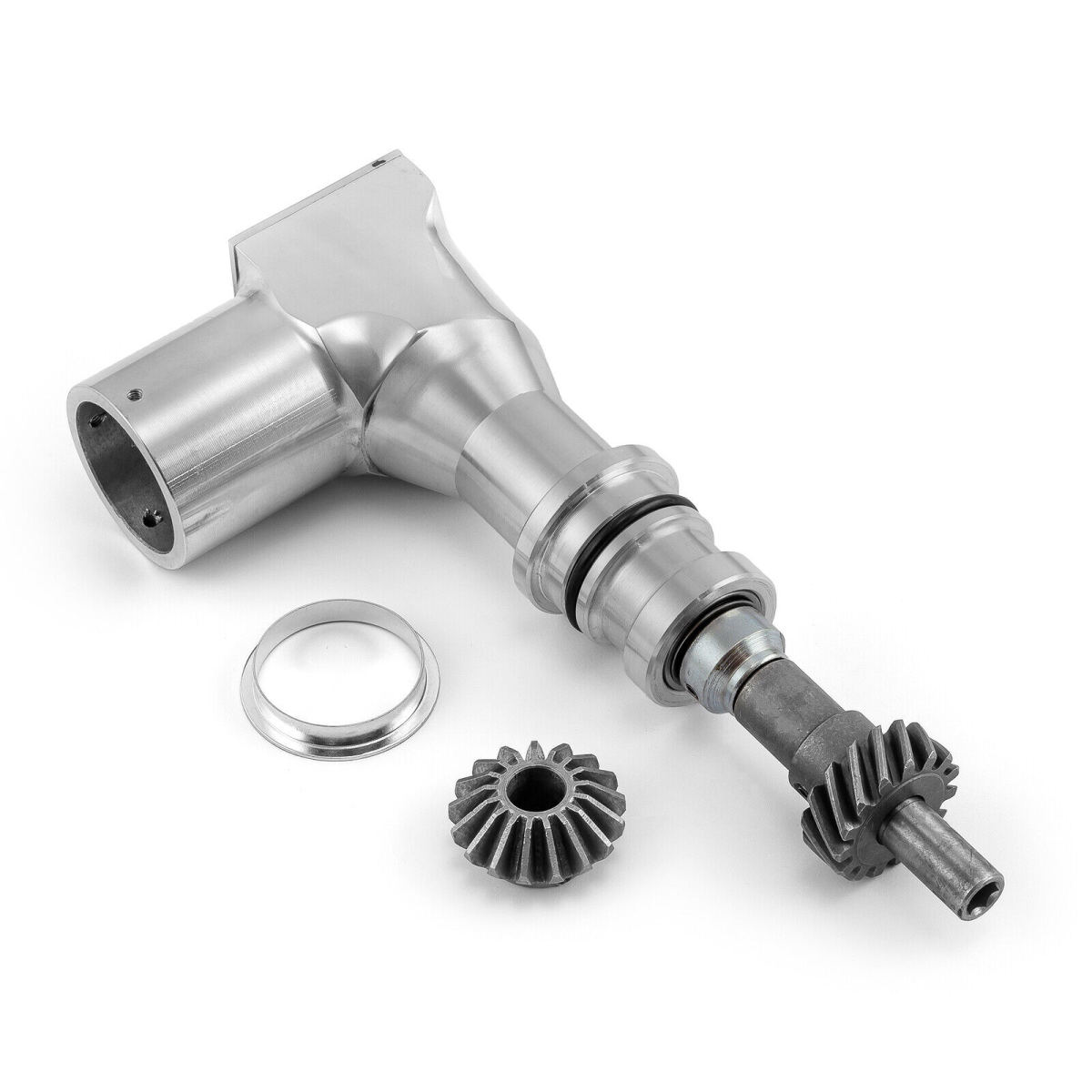
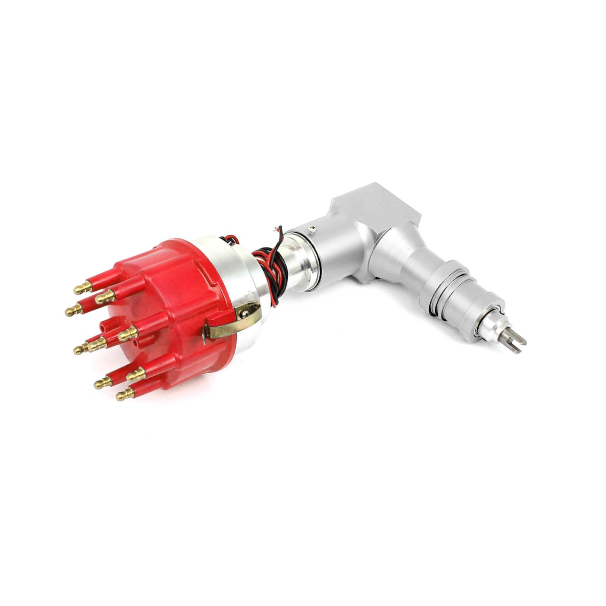
But that isn't exactly short either...
I'd have to mount two pointers at the crank and then I'd most likely have to add spacers on the balancer and then on every other pully due to the shift from the trigger wheels. You all know I don't need less room between my engine and crank pulley and crank triggers are also more expensive.
For the crank trigger, I'm likely using the Pro-M which is 0.10" thick and does not need to add spacers to the pulleys other than a thin one to the water pump (0.10" or less).
I wish someone made a cam sensor that just fit right into the hole and barely stuck out. THAT would be the easiest. The only other one I've found is the MSD, which is slightly taller than the Explorer. Although, I guess most people don't have fitment issues....
Speaking of which, there is this funky thing I thought about using, but would be just as ugly as the belt driven dizzy. It's a right angle adapter for a distributor:
But that isn't exactly short either...
OK, lets try to keep this somewhat factually accurate. (and I'm as guilty as anyone...) But the Crank turns TWICE as fast as the cam. and the CAM turns half the speed of the crank. So there's that.Look at Tom's new Hydroboost bracket. I'm likely going to need to go that route. I saw another thread about an ebay bracket and it looks the same or similar. It uses the same linkage, but literally shifts everything over a little. I have the stock booster, which might work, but I'm leaning towards using that regardless.
Bax, as far as another trigger wheel on the balancer, I've thought about that as well, but the crank turns half as fast as the cam...I thought about telling the computer it has twice as many teeth or something, but it would still pass whatever missing tooth it used for #1 twice so that would not work is my understanding.
If you use the reluctor wheel from the Explorer damper, you can see that it has a missing tooth, or a bump. The computer sees that bump, and it knows it is at TDC either for cylinder #1, or maybe #6. So it needs to know whether it's #1, or #6. Enter the cam phaser. The only reason why an EDIS computer needs to know the cam position, is to discriminate between #1 TDC, and #6 TDC. It also provides a convenient way to set the base timing, so it allows the mounting hardware on the crank trigger to be "mostly good" and it can be trimmed by the cam phaser.
I went out to the garage this morning, and I happen to have a full Explorer front dress, and an explorer timing cover loose. Also have a early SBF timing cover. As I thought, the early cover is deeper in the location of the eccentric. BUT, there is still plenty of room to add a trigger wheel to the cam...BECAUSE the Explorer uses a silent chain, and the Mustang 5.0 uses a double roller chain, and it's about 1/4 inch thicker. (I THINK the SN-95 uses a double roller chain as well..not 100% sure...doesn't really matter.)
So you could pretty easily convert your front dress to Explorer serpentine with the Ford crank trigger. Then you could build a cam trigger wheel to fly past your cam phaser sensor...that you could mount in the accessory boss in the cover. But you will have a challenge with micro adjustments since the phaser will be "fixed." Obviously, any offset between your cam and crank triggers could be mitigated in the code. BUT YOU HAVE TO learn the offset.
But this is where it's gets interesting. If you have a good crank trigger, and you know the cam offset, then why not just let the crank trigger control everything. The only thing you lose is sequential multiport, but Ford triggered bank to bank on every non-HO EFI system during the EEC4 days. And anyone that has ever run a 1-5-4 cam in a 1-3-7 computer knows that it really doesn't matter at all.
So if you tell your EDIS that you are running crank trigger only, and you let your coil packs run waste spark...then the spark is going to happen at the right time, and the fuel is going to be lost half the time. But if you go bank to bank...even that won't matter. You will have to find some way to set initial timing, but that's never not true. here's some pics.
here's some pics.
Attachments


1) Yes, thanks for that clarification, I wrote it so quickly that I miswrote the first part but my explanation was correct. I went back and edited my post. Crank twice as fast.OK, lets try to keep this somewhat factually accurate. (and I'm as guilty as anyone...) But the Crank turns TWICE as fast as the cam. and the CAM turns half the speed of the crank. So there's that.
If you use the reluctor wheel from the Explorer damper, you can see that it has a missing tooth, or a bump. The computer sees that bump, and it knows it is at TDC either for cylinder #1, or maybe #6. So it needs to know whether it's #1, or #6. Enter the cam phaser. The only reason why an EDIS computer needs to know the cam position, is to discriminate between #1 TDC, and #6 TDC. It also provides a convenient way to set the base timing, so it allows the mounting hardware on the crank trigger to be "mostly good" and it can be trimmed by the cam phaser.
I went out to the garage this morning, and I happen to have a full Explorer front dress, and an explorer timing cover loose. Also have a early SBF timing cover. As I thought, the early cover is deeper in the location of the eccentric. BUT, there is still plenty of room to add a trigger wheel to the cam...BECAUSE the Explorer uses a silent chain, and the Mustang 5.0 uses a double roller chain, and it's about 1/4 inch thicker. (I THINK the SN-95 uses a double roller chain as well..not 100% sure...doesn't really matter.)
So you could pretty easily convert your front dress to Explorer serpentine with the Ford crank trigger. Then you could build a cam trigger wheel to fly past your cam phaser sensor...that you could mount in the accessory boss in the cover. But you will have a challenge with micro adjustments since the phaser will be "fixed." Obviously, any offset between your cam and crank triggers could be mitigated in the code. BUT YOU HAVE TO learn the offset.
But this is where it's gets interesting. If you have a good crank trigger, and you know the cam offset, then why not just let the crank trigger control everything. The only thing you lose is sequential multiport, but Ford triggered bank to bank on every non-HO EFI system during the EEC4 days. And anyone that has ever run a 1-5-4 cam in a 1-3-7 computer knows that it really doesn't matter at all.
So if you tell your EDIS that you are running crank trigger only, and you let your coil packs run waste spark...then the spark is going to happen at the right time, and the fuel is going to be lost half the time. But if you go bank to bank...even that won't matter. You will have to find some way to set initial timing, but that's never not true. here's some pics.
2) Yes, agreed, very well explained, thanks.
3) I have a timing gear set instead of chain, but yes, it used to have a double roller. Not sure of the thickness differences between those or if my gear would fit in the explorer. According to Summit, it fits all years.
4) So yes, I could prob convert to Explorer front dress, but it sounds like a headache since I already have everything serpentine and don't really see what I'd get out of that. I worry about what to do with my AC compressor (what have you guys done who have the VA system and a 5.0?). Is it an easy swap? I'd also need a new balancer, correct? And then yes, the thought of not being able to adjust the timing on that sensor stresses me out. The Explorer setup I've read is bad enough. With the MSD sensor, all I need to do is move it just slightly as it has an led light to tell me the right place. I believe I turn it to make the light go off, which indicates it's in front of the pickup, then back off just until the light turns on. Just like the full MSD Cam Sync.
5) Yes, back to the wasted spark scenario. It just seems like a step backwards. I know it works, and even if I never subject myself to a situation where I bring detonation into the mix, I'm still firing my plugs and coils twice as often s necessary increasing wear. I just think it's not ideal even if it does work. I think it's better than a belt driven distributor but I see it as a last resort.
Thanks again for the detailed post, I appreciate it. Gives me more to think about.
4) So yes, I could prob convert to Explorer front dress... to get a robust crank trigger, and a serpentine system that is compatible with my future vintage air compressor. It also adds another inch between fan and radiator, and this would help to keep my engine cool, and keep James Roney happy.Thanks again for the detailed post, I appreciate it. Gives me more to think about.
5) Yes, back to the wasted spark scenario. It just seems like a step backwards. I know it works, and even if I never subject myself to a situation where I bring detonation into the mix, I'm still firing my plugs and coils twice as often s necessary increasing wear. I just think it's not ideal even if it does work. I think it's better than a belt driven distributor but I see it as a last resort.
What engine management are you running? EDIS or EEC-4? It's going to matter. I've never understood how an Explorer comes with 4 coil packs, and 8 spark plugs. I always wondered how the coil knew which plug gets fired...But I run an A9L EEC4 system, and I throw coil packs in the scrap bucket. Do they have a separate firing event? Sorry, I just don't know.
You will never have to convince me that your belt drive distributor is a last resort. I think it is a non-starter. I'd run an Explorer GT40 upper all day long before I scabbed that distributor up there. Gotta go. Good luck. I won't be back on the computer for a few days. Not mad, but I'm not getting any work done.
I'm running Megasquirt 3 using PiMPxs and I plan to have coil near plug, 8 coils. I have an A9P (pretty similar), but between my BXR and my 30lb injectors, I would need a new mass air meter and whole lot of other stuff and would rather upgrade anyway.
Explorer comes with 4 because it fires both cylinders at the same time (one on compression and one wasted on exhaust), that's wasted spark.
Agreed, I should step away as well! This stuff is addicting!
Explorer comes with 4 because it fires both cylinders at the same time (one on compression and one wasted on exhaust), that's wasted spark.
Agreed, I should step away as well! This stuff is addicting!
So, here is the 3d printed piece. It’s pretty good. I threaded the hole and put the sensor in and tested it and it works great.
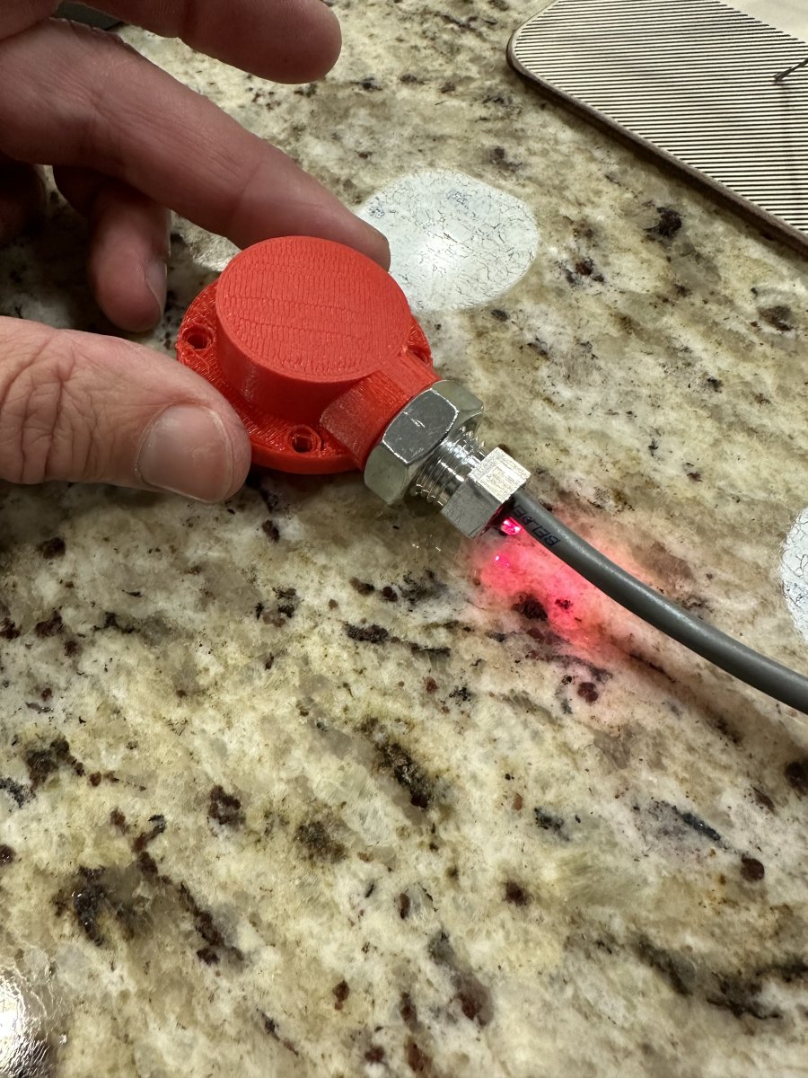
Only thing I need to do is figure out what I want to mount the magnet to. I was planning on using the top of the explorer cam sync shaft but the metal is too thin to be ideal to mount this magnet assembly securely. I would worry about it flying loose and that would suck. Just need to find the right thing with 5/16-18 thread. Common bolt size, shouldn’t be too hard and still a 0.383” hole.
Magnet assembly:
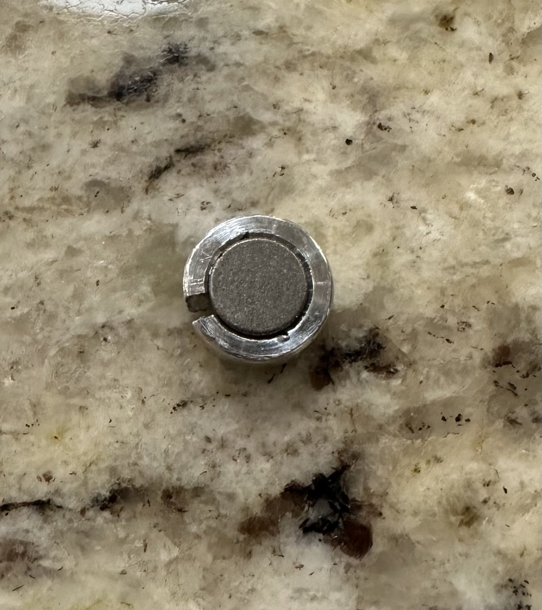
Only thing I need to do is figure out what I want to mount the magnet to. I was planning on using the top of the explorer cam sync shaft but the metal is too thin to be ideal to mount this magnet assembly securely. I would worry about it flying loose and that would suck. Just need to find the right thing with 5/16-18 thread. Common bolt size, shouldn’t be too hard and still a 0.383” hole.
Magnet assembly:

Thanks, I think I have it all figured out. I ordered the parts I need for the rest of it today….too bad McMaster Carr reams you on both price and shipping but I liked the bolts I found on their site to attach the cover.
Anyone ever attach a magnet like that above? It did not come with any attachment instructions really, it just says I have to drill a hole (no shit). I emailed MSD support to see what they say. But will either be press fit or epoxy (or a little of both).
Using a stainless steel 1” stud into the end of the existing threaded shaft, which will attach to a 1” diameter aluminum standoff with the same 5/16-18 threads:

So I’ll have to drill a hole in the side of that to mount the magnet and that piece will spin in the housing.
Was debating using stainless and welding them together but I don’t want anything that could potentially interfere with the pickup and aluminum will not (why is has an aluminum retainer around the magnet…so will prob just JBweld on the threads unless someone else has any other ideas? Maybe just Loctite would be better?
I went back and forth on what to do for the distributor hold-down and decided that I will have it go on top of both pieces and press down, makes the most sense. I’ll just need a longer bolt and some spacers so that if can press evenly, which I ordered as well. I might get a different hold-down, but can figure that out at the end of this.
I also thought of just trying to use a 3D printed piece since it’s printed at 220° Celsius, but since it would suck if it failed I’ll get that made in metal when I’m sure it all works. I made some minor sizing changes in the design and buddy is printing a new one hopefully today.
Anyone ever attach a magnet like that above? It did not come with any attachment instructions really, it just says I have to drill a hole (no shit). I emailed MSD support to see what they say. But will either be press fit or epoxy (or a little of both).
Using a stainless steel 1” stud into the end of the existing threaded shaft, which will attach to a 1” diameter aluminum standoff with the same 5/16-18 threads:
So I’ll have to drill a hole in the side of that to mount the magnet and that piece will spin in the housing.
Was debating using stainless and welding them together but I don’t want anything that could potentially interfere with the pickup and aluminum will not (why is has an aluminum retainer around the magnet…so will prob just JBweld on the threads unless someone else has any other ideas? Maybe just Loctite would be better?
I went back and forth on what to do for the distributor hold-down and decided that I will have it go on top of both pieces and press down, makes the most sense. I’ll just need a longer bolt and some spacers so that if can press evenly, which I ordered as well. I might get a different hold-down, but can figure that out at the end of this.
I also thought of just trying to use a 3D printed piece since it’s printed at 220° Celsius, but since it would suck if it failed I’ll get that made in metal when I’m sure it all works. I made some minor sizing changes in the design and buddy is printing a new one hopefully today.
Last edited:
That's a really good thought! As for threaded magnets, I was sure this would be threaded when it came so I'm a little surprised but no. I did a search to see if there are any and well, there isn't much around. Found this, but it's not like its the magnet that's threaded. It;s a magnet that is probably epoxied in there and they charge $40 to epoxy it for you.With the aluminum you may be able tp peen the edge of the magnet into place as some extra insurance. Do they make threaded magnet inserts?
The magnet from MSD though, is also double sided and only one side triggers the sensor, so I'd be worried about getting an incorrect magnet if I bought another one. Also, it is EXTREMELY strong. Maybe what I should do, is tap the hole, put in a steel stud (similar to that pic) that the magnet will be attracted to and then epoxy it in there so it has the magnet making it want to stay as well as the epoxy. Should be good with that.
I'm honestly most concerned with the threads of the stud in the distributor shaft coming loose. Esp since it spins counter-clockwise.
Anyone have any thoughts on that?
Seems like this might be best:
Would that work? Or would it be better to drill a hole through and put a press pin like they do when they put a dizzy together? I could also drill a hole through the top of that standoff just enough to recess a bolt instead of a stud from the bottom.
Ok, I ordered some pins. I guess I answered my own question. There's a reason they do it that way. The pin can't come out and if the pin can't come out, then the assembly can't unscrew.
These look perfect:
Last edited:
Interesting... I was doing some more searching and figured I'd find other MSD kits that have the same magnet and see if they have any better instructions and whaddya know?
Not sure why they wouldn't put the same magnet instructions in every kit that has this magnet, since ya know, it's the same magnet and all...
This is what they say:
The magnet requires a 0.250” dia. hole. If the magnet is to be pressed in it should be prepared as 0.248 +/- 0.0005. If the magnet is not pressed in it should be secured with an epoxy inside the hole of a 0.25” mill bit. The magnet is 0.20” deep. If the magnet is to be mounted in a steel rotational assembly the supplied aluminum sleeve is required to prevent diffusing the magnet in the assembly. The aluminum sleeve requires a prepared hole measuring 0.375” +/- 0.0005 or a 0.375” bit, respectively.
So looks like pressing it is, but I might throw a little epoxy in the bottom of the hole anyway. Couldn't hurt.
I also found a screw in magnet for another sensor from MSD but at like $50+, I'm ok with press in at this point. Maybe if I'd noticed when I ordered I would have. And if pressed it or epoxied, it's not like the magnet can go anywhere. There won't be any room for it to go. It's a 1" cylinder spinning inside a 1" hole.
Not sure why they wouldn't put the same magnet instructions in every kit that has this magnet, since ya know, it's the same magnet and all...
This is what they say:
The magnet requires a 0.250” dia. hole. If the magnet is to be pressed in it should be prepared as 0.248 +/- 0.0005. If the magnet is not pressed in it should be secured with an epoxy inside the hole of a 0.25” mill bit. The magnet is 0.20” deep. If the magnet is to be mounted in a steel rotational assembly the supplied aluminum sleeve is required to prevent diffusing the magnet in the assembly. The aluminum sleeve requires a prepared hole measuring 0.375” +/- 0.0005 or a 0.375” bit, respectively.
So looks like pressing it is, but I might throw a little epoxy in the bottom of the hole anyway. Couldn't hurt.
I also found a screw in magnet for another sensor from MSD but at like $50+, I'm ok with press in at this point. Maybe if I'd noticed when I ordered I would have. And if pressed it or epoxied, it's not like the magnet can go anywhere. There won't be any room for it to go. It's a 1" cylinder spinning inside a 1" hole.
I’m on my 4th revision of my 3D cam sync and I just finalizing stuff and think I’m close to ordering but keep getting frustrated that every time I get this printed, my screws do not fit in the holes.
Just a heads-up, that it’s nice that McMaster Carr puts spec sheets with dimensions for stuff, but don’t get your parts machined until you’re sure it’s the same…these screws are bigger and I’m glad I finally measured them.
Here is the last revision though, I did make it a tiny bit bigger to fit properly, give enough clearance on the inside, and then extend the threaded part for a little more strength.
Need to get the real part and then drill a hole in the cylinder for the magnet and press it in, and a little work to the original plug to make them fit together.
Just a heads-up, that it’s nice that McMaster Carr puts spec sheets with dimensions for stuff, but don’t get your parts machined until you’re sure it’s the same…these screws are bigger and I’m glad I finally measured them.
Here is the last revision though, I did make it a tiny bit bigger to fit properly, give enough clearance on the inside, and then extend the threaded part for a little more strength.
Need to get the real part and then drill a hole in the cylinder for the magnet and press it in, and a little work to the original plug to make them fit together.
Attachments

And just did a little more so I could be sure this design works. First off, this freeze plug cap on the cam plug is seriously in there, like JB weld or something, it’s not coming out and I’d rather it not anyway as I’d like the tolerances to be tight and keep oil out so hope it does or maybe I could fill these bushing holes with silicone or something?

To keep it tight, I used a 1” hole saw and made sure the hole saw was proper tolerance and it is perfect.
Then I cleaned it up a little and checked fit.


It all seems perfect. Won’t fit flat together until I cut away a little of the plug to fit the sync sensor tube and I don’t want to do that until I have the final piece but I think I’m good to go. All measurements check out.
To keep it tight, I used a 1” hole saw and made sure the hole saw was proper tolerance and it is perfect.
Then I cleaned it up a little and checked fit.
It all seems perfect. Won’t fit flat together until I cut away a little of the plug to fit the sync sensor tube and I don’t want to do that until I have the final piece but I think I’m good to go. All measurements check out.
Similar threads

- Replies
- 7
- Views
- 2K


