• Welcome to ClassicBroncos! - You are currently viewing the forums as a GUEST. To take advantage of all the site features, please take a moment to register. It's fast, simple and absolutely free. So please join our community today!
    If you have problems registering or can't log into your account, please contact Admin.

Turn Signal Wiring

Joined
Apr 27, 2015
Messages
2
Greetings,

I have what I have always believed to be a 1969 Bronco with a 3 Speed column shift. I have started a wiring project and have ran into some confusion, in my Turn Signal Wiring. My wiring doesn't seem to match the wiring diagrams that I have seen. My wiring is as follows:

White/Blue Stripe - Right Front Marker Light
Green/White Stripe- Left Front Marker Light

Green/Orange Stripe - Left Rear Turn Signal
Orange/Blue Stripe - Right Rear Turn Signal

Blue/Green Stripe- Horn ( horn sounds when grounded)

Solid Green wire- Brake Switch Wire

Light Blue Solid wire- Turn Signal Flasher

Solid Yellow Wire- ??? Unsure larger gauged wire than rest. Possible Ground?

Can anyone make sense of this? Any help is appreciated. Thanks Guys!
 

Viperwolf1

Contributor
electron whisperer
Joined
Aug 23, 2007
Messages
24,348
Sounds about right for the early colors. Yellow is power to the horn switch. Yours might have been converted to use a horn relay or the horn is just wired wrong.

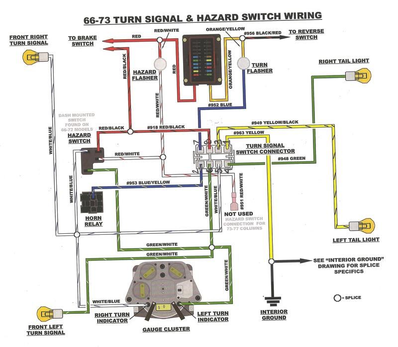
These pics are brand new and show the locations of the wires and what their functions are. That way colors don't matter. Use the locations to verify the colors.

Light Blue=12v from turn flasher to turn switch, circuit #44
white-blue=right front turn and indicator lamp, circuit #2
orange-blue=right rear brake and turn lamp, circuit #5
green-white=left front turn and indicator lamp, circuit #3
green-orange=left rear brake and turn lamp, circuit #9
green or red-black=12v brake switch to turn signal switch, circuit #810
yellow=12v headlight switch to horn switch, circuit #460
blue-yellow=horn switch to horn, circuit #482
 

Attachments

  • 66-73 turn sw.jpg
    66-73 turn sw.jpg
    85.6 KB · Views: 243
  • 66-73 turn sw2.jpg
    66-73 turn sw2.jpg
    75.1 KB · Views: 203
OP
OP
O
Joined
Apr 27, 2015
Messages
2
Thanks Viper,

Horn must be wired wrong because is works, when center cap of steering wheel is pushed it grounds out and sounds the horn.

How should it correctly be wired?
 

Viperwolf1

Contributor
electron whisperer
Joined
Aug 23, 2007
Messages
24,348
Thanks Viper,

Horn must be wired wrong because is works, when center cap of steering wheel is pushed it grounds out and sounds the horn.

How should it correctly be wired?

Just like it says above. 12V on yellow wire. Blue-yellow wire is then switched 12V (when horn button is pressed) to go to the horn. Horn must be grounded.

It sounds like you have 12V on the horn ground terminal though. That would be where it's wired wrong. Might be a reason for it, maybe yellow wire doesn't make it all the way to the horn or something.
 

Teal68

Contributor
Bronco Guru
Joined
Mar 28, 2013
Messages
2,595
Loc.
Inlet Beach
Sounds about right for the early colors. Yellow is power to the horn switch. Yours might have been converted to use a horn relay or the horn is just wired wrong.

These pics are brand new and show the locations of the wires and what their functions are. That way colors don't matter. Use the locations to verify the colors.

Light Blue=12v from turn flasher to turn switch, circuit #44
white-blue=right front turn and indicator lamp, circuit #2
orange-blue=right rear brake and turn lamp, circuit #5
green-white=left front turn and indicator lamp, circuit #3
green-orange=left rear brake and turn lamp, circuit #9
green or red-black=12v brake switch to turn signal switch, circuit #810
yellow=12v headlight switch to horn switch, circuit #460
blue-yellow=horn switch to horn, circuit #482

Viper,
This is way helpful, and I thank you very much for posting information like this. I have been struggling with my painless harness and the turn signal pins for the last two days and just came across this post. Does this look correct as the numbers relate to your images:


This seems like the easiest way to figure this. Just remove the steering wheel and coordinate your numbers and painless's schematic....at least for me!

Thank you sir,
Tyler
 

Viperwolf1

Contributor
electron whisperer
Joined
Aug 23, 2007
Messages
24,348
Viper,
This is way helpful, and I thank you very much for posting information like this. I have been struggling with my painless harness and the turn signal pins for the last two days and just came across this post. Does this look correct as the numbers relate to your images:


This seems like the easiest way to figure this. Just remove the steering wheel and coordinate your numbers and painless's schematic....at least for me!

Thank you sir,
Tyler

Yes that looks correct. Keep in mind there is a minor difference in the horn circuit. Stock harness through '73 used no horn relay. Painless added a relay and that changed the yellow wire from 12V to ground. The relay is a better design.
 

Teal68

Contributor
Bronco Guru
Joined
Mar 28, 2013
Messages
2,595
Loc.
Inlet Beach
Yes that looks correct. Keep in mind there is a minor difference in the horn circuit. Stock harness through '73 used no horn relay. Painless added a relay and that changed the yellow wire from 12V to ground. The relay is a better design.


Thank you Viper, and thanks for the answer in the other thread too. You nailed it, that one wire still had me had me questioning my numbered layout. I was not smart enough to think about it being a ground relay in the painless conversion....even though the instructions are pretty clear.
 

Teal68

Contributor
Bronco Guru
Joined
Mar 28, 2013
Messages
2,595
Loc.
Inlet Beach
Viper, I just wanted to says thanks. That did the trick, and made my life a lot easier!
 
Top