The gauges are still acting up. When I turn the key to 'ON' the fuel gauge pegs out, even though I know I have half a tank. When I start the engine the oil pressure gauge pegs out as well.
The ammeter, and the temp gauge don't move.
Not sure about the temp gauge, but the ammeter not working is correct for the current setup. That Black w/yellow wire that's cut under the hood is your proof.
The gauge cluster fuse at the fuse block has popped twice randomly and another time when the gauge regulator arced on the metal dash panel.
I'll let Eric talk about that if he catches this. I'd have to study the diagram again, but he can probably say whether that would be an issue with the IVR, ground, previous damage done by the pump, or something else.
While I was fishing around under the dash, I found that the instrument panel voltage regulator had broken off from the back of the panel. If I unplug the regulator, the fuel and oil gauges stop sending (expected).
The volts from the black / green wire (from fuse block to regulator) reads 13.5 v or so. The regulator is putting out 12.4 v or so.
Now the real surprise was when the regulator was plugged in, I attempted to push it up into the dash and the body of the regulator arc'ed out on the grounded metal dash popping the 10 amp fuse. I then checked the body of the regulator, and it is reading 13.5 v. IS THIS RIGHT? Looking up into the back of the gauge cluster where the original tab held the regulator, it looks like it is supposed to be grounded onto the panel.
I am lost at this point. I purchased a spare gauge regulator ($65 !) and it is acting the same as the OEM regulator.
The regulator HAS to be grounded (to the cluster is best) or it will not function properly. Probably why you are getting full voltage and pegged gauges and sparks.
I would expect it to show the voltage with a meter attached to the case, since the case is the ground that completes the circuit. But I don't know for a fact what it should read while it's not bolted down vs bolted down.
And yes, I would expect at least some little sparkage when you touch a ground because that's what happens sometimes when you complete any circuit.
So not saying it's right, but not saying it's wrong yet either. One of the others can answer that unequivocally.
First things first. Attach the new regulator to the cluster and try again. Not sure if you could have damaged the new one with all the fiddling, but might as well try it and see what happens.
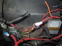
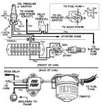
NOW as far as the replacement 63 amp, single wire alternator and the external voltage regulator: See pic #3.
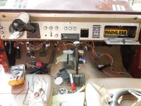
Still haven't seen a pic of the alternator I don't think. Can you show that too please? Might help figure this out.
But a 1-wire alt does not use an external regulator, and a GM alternator will probably not work with a Ford regulator wired like ours. It might work if the wires were changed, or not, but probably not as it sits.
Besides, what good does an external regulator do when the Orange Field wire is disconnected anyway?
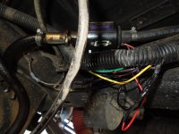
The heavy gauge blk/yel wire (coming from the loom) and the orange wire are terminated. The split yellow wire - one goes to a cylinder 'thingy-oh' (speak up if you know what that is) and the other goes into the loom. The single heavy gauge wire from the alt. goes to the maxi-fuse, then on to the starter solenoid.
All of that is again why your ammeter is non-functioning. Even if the Black w/yellow wire was still being used, the single heavy gauge wire direct to the battery would have negated anything it was trying to do. Right now 100% of your charging power goes straight to the battery (via the starter relay) and none goes through the ammeter.
The Yellow wires are 1) system voltage sensing from the battery, and 2) the radio noise suppressor (the 'thingy-oh') so should have full battery voltage all the time. Key on OR off.
According to the PAINLESS wiring diagram, the 10 ga. blk/ylw wire should be going to the ammeter input via the maxi-fuse. I honestly don't know if the ammeter gauge has ever worked.
It might have, but it never has in this particular configuration.
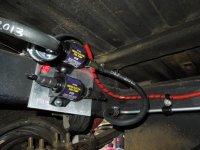
The Maxi-Fuse is supposed to be on the Black wire from the starter relay/solenoid post. If it's inline with the Black w/yellow wire that is cut, then it's literally not protecting anything right now, except for if that wire happens to touch a ground and short out.
Can you trace the Black wire (same gauge as the Black w/yellow) from the starter relay and see where it goes?
After looking at pics of alternators, with blade types that the old one had, it looks to be an AC Delco externally regulated, but not hooked up with the external voltage regulator.
Which would explain why it's not working. Or is it? Since you have 13.5 volts at the battery, it sounds to me like it's charging at least some of the time.
Can you get a reading at the battery with the engine running? Should be 14 to 14.5 volts, generally speaking.
Let us know what you get.
There is still an issue with the fuel pump pulsing. Before wiring in the new pump, the pump would pulse to the tune of either turn signal indicator. Now, it only pulses with the right turn signal on. So there is still something going on, maybe with a ground.
Could be the ground, but it sounds like you might want to take the power for the pump from somewhere else besides that wire at the fuse panel.
If that Green w/black wire is for the IVR, find another one. If it's for the general accessory circuit (if there is such a thing in this harness) then tie it to the pump through a relay anyway. This gets power straight from the battery without any of the fussiness and funny business you seem to be experiencing.
Pump should be through a relay anyway, in my opinion. If only to give you more options.
What additional problems can be causing my gauges to peg out?
1. Sending units failed, wired incorrectly, or somehow otherwise getting a straight path to ground.
2. That same bad IVR we were talking about.
3. Some other wiring discrepancy from the PO at the cluster.
4. Whether it's a possible cause or not, make sure the cluster is grounded to the dash, and that the dash is grounded to the body, and that the body is grounded to the battery at one hundred and sixty three locations of your choice. ;D
How's the Scotch holding out?
Paul