• Welcome to ClassicBroncos! - You are currently viewing the forums as a GUEST. To take advantage of all the site features, please take a moment to register. It's fast, simple and absolutely free. So please join our community today!
    If you have problems registering or can't log into your account, please contact Admin.

Engine Swap: Cummins R2.8

OP
OP
Digger556

Digger556

Sr. Member
Joined
Aug 8, 2013
Messages
801
After fitting up the expansion tank and making some brackets, I bought a new unit for the install.
51118229374_163549149c_o.jpg


51118229364_0c2e88e266_o.jpg


And my power steering reservoir showed up and got modeled into CAD
51118387633_837f7a5d4d_o.jpg


I ordered exhaust wrap to help keep heat in the pipe between the turbo and the DOC.
51118476226_9e78449b16_o.jpg


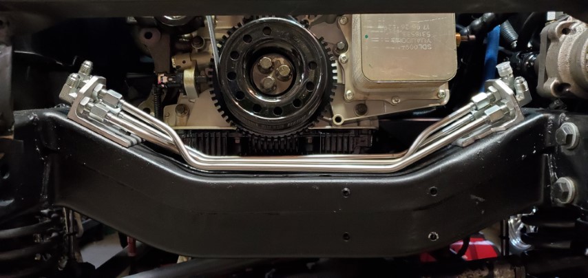
The last large mechanical job was plumbing the power steering system. With the pump on the right side of the engine, limited space for a reservoir and hydroboost combined with power steering, spacing is tight and there are lots of hoses running around. To keep things clean and provided additional cooling surfaces, I ran SS hard lines between the sides of the engine bay. 3 total were required for pressure and 2 returns. I started with some brackets:
51117908302_7012db5706_o.jpg


...and laid out where the soft lines would run. With position of various components and fitting angles, I needed to have the pressure line and one return cross over each other.
51118476121_dd26191d9b_o.jpg
 
OP
OP
Digger556

Digger556

Sr. Member
Joined
Aug 8, 2013
Messages
801
After a few tries, all three lines were in.
51119270235_2fe0f63cd5_o.jpg

51118388043_0062420767_o.jpg


The power steering reservoir needed a mounting bracket. Starting with some aluminum sheet:
51118388033_fa956d873a_o.jpg


Punching some holes:
51119270510_9176e2f81f_o.jpg

51118476456_2858d1910c_o.jpg


Add some dimple dies
51119270485_00ea350b29_o.jpg


And paint:
51117908502_ef3c9b8900_o.jpg

51119270230_689e529da1_o.jpg

51118476441_5334f4c9f3_o.jpg


Installed
51119270465_f86149ca0c_o.jpg

51118387978_6905788661_o.jpg
 
OP
OP
Digger556

Digger556

Sr. Member
Joined
Aug 8, 2013
Messages
801
I didn't take many photos, but I spent a few night building and running hoses
51117908232_47b51d37df_o.jpg


I'm trying out spring clamps over the usual worm drive stuff. Seems like it is hard to find good quality worm clamps anymore.
51118476406_d996b05bc6_o.jpg


51118387953_259ba6f54d_o.jpg

51118229494_170b1f53d9_o.jpg


The reservoir lines are close to the turbo compressor, so I added a heat wrap to protect them.
51117908452_c7437be905_o.jpg


Without a running engine, I purged the system with a drill
51119270405_871706e2ef_o.jpg
 
OP
OP
Digger556

Digger556

Sr. Member
Joined
Aug 8, 2013
Messages
801
Getting the power steering wrapped up puts me in the home stretch. I needed to dig into the interior and get the gas pedal mounted. The Cummins kits uses a drive-by-wire throttle with redundant circuits
51118229329_900da32810_o.jpg
[/url]

Removing so many factory pieces left a lot of holes in the firewall. I made a patch to close it back up.
51118387923_54f336c832_o.jpg


Nothing fancy, but it gets the job done.
51118476376_d5466e1984_o.jpg


I spent a few nights deciding how to mount the computer.
51118387898_8642bc30f7_o.jpg


A new battery tray was ordered and needed to be trimmed for wiring clearance
51119270190_5ac87bbff2_o.jpg

51118229469_6a113ec2e5_o.jpg
[/url]
 
OP
OP
Digger556

Digger556

Sr. Member
Joined
Aug 8, 2013
Messages
801
Since I will have power ports front and rear with a winch and a more powerful starter, heavier 2/0 battery cable was ordered and new cables made. This was another chance to improve things over the last iteration.
51119270365_ac585b934a_o.jpg


Making my own coolant hoses required grafting 2 diameters together. Trying to keep things clean looking, I ordered some Gates heat shrink hose clamps
51118387868_9607a1a5f2_o.jpg


The flasher modules were also upgraded with all lights going to LEDs
51118229444_2f088fecd3_o.jpg


Back to the cooling system, the new fan needed to be mounted to the Explorer radiator
51117908422_1a03e16d11_o.jpg

51118229314_ca6387b567_o.jpg
 
OP
OP
Digger556

Digger556

Sr. Member
Joined
Aug 8, 2013
Messages
801
The Cummins lacks any ports to plumb an additional MAP sensor for my boost gauge. By dumb luck, the CAC has an extra port for a sensor. I just needed to make an adapter to hook it up.
51118229424_5c55291430_o.jpg


51118476336_0f1b466163_o.jpg


51118229414_8791f8973b_o.jpg


51117908402_a204d04bb7_o.jpg


51118387658_63639f7d95_o.jpg


51118229404_ec896e724c_o.jpg
 
OP
OP
Digger556

Digger556

Sr. Member
Joined
Aug 8, 2013
Messages
801
The Cummins has a large bulkhead fitting to pass electrical through the firewall. I also am adding a 2nd fitting for the gauge sensor wires
51118476316_a2bc7459a2_o.jpg


A bulkhead plate needed to be made
51118387793_6d13c7dce8_o.jpg


51118476296_3d8be7de2d_o.jpg


51118476271_74e2cb4a54_o.jpg


51118229284_1a9169a9eb_o.jpg


Since the front end was tore apart, I pulled the trigger on upgraded headlights
51118476261_9e9db59efe_o.jpg
 

JeffG

Contributor
Sr. Member
Joined
May 7, 2004
Messages
513
Loc.
San Antonio, TX
Great build!! Love the detail you are putting into it and the documentation for others.

What is the tool pictured with the bulkhead plate?
 

ntsqd

heratic car camper
Joined
Jan 30, 2005
Messages
5,953
Loc.
Upper SoKA
Looking good, home stretch? The last 10 is 90 is really looking to be true here.

Years ago Tom Lee built us a PS system and he was rather forceful that we not use any machined angle fittings in 'his' system. If we needed to change direction tighter than could be done with a hose that it be done only in formed tube type hose ends. He was all about reducing and eliminating places for cavitation to occur. Because of that the 90° bulkheads really caught my eye. I'm guessing that they're required due to space constraints.

The tool looks to me to be a panel broach operated by a porta-power pull cylinder.
 
OP
OP
Digger556

Digger556

Sr. Member
Joined
Aug 8, 2013
Messages
801
Great build!! Love the detail you are putting into it and the documentation for others.

What is the tool pictured with the bulkhead plate?


It's a Harbor Freight hydraulic knockout kit.
image_11983.jpg


https://www.harborfreight.com/hydraulic-punch-driver-kit-96718.html

I also bought inch-sized knockout dies from TemCo.
https://temcoindustrial.com/punch-die-set-non-conduit-5-8-3-4-7-8-1-1-125-1-25-1-375-1-50-1-625-1-75-1-875-2-00/


It's been great for making quick, clean holes. Way better than hole sawing. The HF kit makes holes for condiut sized fittings. The Temco dies make holes in even 1/8th inch increments.
 
OP
OP
Digger556

Digger556

Sr. Member
Joined
Aug 8, 2013
Messages
801
Looking good, home stretch? The last 10 is 90 is really looking to be true here.

Years ago Tom Lee built us a PS system and he was rather forceful that we not use any machined angle fittings in 'his' system. If we needed to change direction tighter than could be done with a hose that it be done only in formed tube type hose ends. He was all about reducing and eliminating places for cavitation to occur. Because of that the 90° bulkheads really caught my eye. I'm guessing that they're required due to space constraints.

The tool looks to me to be a panel broach operated by a porta-power pull cylinder.


Makes sense. Packaging issues over ruled plumbing ideals with this build. My reservoir is pretty large though so oil will get a chance to deaerate and cool before making another trip through the system.
 
OP
OP
Digger556

Digger556

Sr. Member
Joined
Aug 8, 2013
Messages
801
Looking great, Jesse!

Todd Z.


Thanks Todd!


I got into the wiring this weekend. Everything under the hood is wired except for the engine fan. I made some brackets for routing the chassis and engine harness past the radiator.
51124718143_a9e34446c0_o.jpg


Any wires that didn't have labels printed on them were given a labeled shrink tube so I don't have to guess later if the harness needs service.
51124243097_00d89c64e9_o.jpg

51124718113_f07f9173b9_o.jpg


The power distribution box is buttoned up and 2/0 cables run to the battery. One red goes to the starter, the other connects to the 200 amp relay and on to the power distribution. Blacks are chassis and block grounds.
51124555924_ab2db3171c_o.jpg


I positioned the lower radiator hose, marked its orientation and applied the PowerGrip hose clamps. The black port will attached to the expansion tank.
51124718098_7b0a8a37d6_o.jpg
 
OP
OP
Digger556

Digger556

Sr. Member
Joined
Aug 8, 2013
Messages
801
I ended the weekend by putting her face back on, hooking up the LED headlamps and turn signals. I found some LED turn lamps that were very low profile, which was needed to fit in front of the CAC.
51124555934_e067bb69d6_o.jpg

51125615805_20683955f1_o.jpg


51125615875_1eb94eb421_o.jpg

51125615870_dd810b5b0e_o.jpg

51124243042_fbca193314_o.jpg
 
OP
OP
Digger556

Digger556

Sr. Member
Joined
Aug 8, 2013
Messages
801
Wiring the dash side harness was the last step to get the engine running. I pulled the whole thing apart and removed some redundant wiring that came with the Centech harness, like dual hazard circuits.

51158162737_5f38bb2450_o.jpg


I also pulled apart the Cummins harness and shorten it quite a bit.
51159058003_071717bd1a_o.jpg

51158159532_230bbf898e_o.jpg


Then put things back together
51158162727_8921371557_o.jpg

51158818546_4cc0864c4a_o.jpg


I finally received all the t-fittings I needed to complete the cooling system air bleed lines
51159058038_48f191e115_o.jpg


And made an adapter to connect the reservoir return to the lower radiator hose
51158816661_a975faa281_o.jpg

51158157627_3f06b9cc04_o.jpg
 
OP
OP
Digger556

Digger556

Sr. Member
Joined
Aug 8, 2013
Messages
801
Tonight I finished the last electrical connections, assembled the intake, added fluids, dumped 5 gallons of diesel in the tank and pushed her outside...

51159926125_67b054c455_o.jpg

51159601119_19942071d5_o.jpg

51158816586_549ca971ac_o.jpg


51159926135_0d597e709c_o.jpg


I had to crank it quit a bit, even after priming the fuel lines, but the R2.8 popped right off on the 2nd try.
[youtube]OHDu5D8P15Y[/youtube]
https://www.youtube.com/watch?v=OHDu5D8P15Y
 
OP
OP
Digger556

Digger556

Sr. Member
Joined
Aug 8, 2013
Messages
801
Another quick video:
https://www.youtube.com/watch?v=M2Psvz1y6PQ

Initial impressions:
The R2.8 is really smooth for a diesel and not as loud as I expected. There was no noticeable diesel smell just standing around listening to it idle. I had to get my nose right to the tail pipe to really smell it.

Driving around the neighborhood, its a little sluggish off the line, but the boost comes on quick and then it really pulls hard, even at low rpm. Below 2000rpm, this engine pulls better than my 351W did. I will say the transmission adapter added a lot of rotating weight which doesn't help the engine get up to speed. Overall driving was pleasant. One surprise was chirping the rear tires by getting out of the gas quickly. I tried it a few times just to be sure, but in low gears, the engine pulls down fast, maybe due to the throttle body in the intake.

I need to button up a few things tomorrow and double check everything is tight and leak free, then I'll go for a longer drive.
 

toddz69

Sponsor/Vendor
Bronco Guru
Joined
Nov 28, 2001
Messages
11,205
Very cool, Digger!! Congrats on this big moment - must feel really good to have a running, driving Bronco again after all this hard work!

Todd Z.
 

JeffG

Contributor
Sr. Member
Joined
May 7, 2004
Messages
513
Loc.
San Antonio, TX
I agree. Very impressive work on the install and you did a great job documenting everything for others who may want to install this engine. I'm surprised this engine can't be shipped to Texas.
 

Attachments

  • R2.8.jpg
    R2.8.jpg
    28.5 KB · Views: 95
Top