• Welcome to ClassicBroncos! - You are currently viewing the forums as a GUEST. To take advantage of all the site features, please take a moment to register. It's fast, simple and absolutely free. So please join our community today!
    If you have problems registering or can't log into your account, please contact Admin.

Track bar / drag link geometry

Yeller

Contributor
Bronco Guru
Joined
Mar 27, 2012
Messages
6,876
Loc.
Rogers County Oklahoma
I’ll try to carefully tread on the radius arm topic, my gut response many here would find offensive. My goal is never to tell anyone how to build their rig, I will strongly suggest, but never dictate. I want to be educational and will never tell anyone their ideas or what they have built is terrible unless I see something that makes me fearful for the safety of yourself and/or those bystanders. So if you like radius arms please build them, but it won’t stop me from politely trying to talk you out of it.

If doing that level of work, cut the upper link off the radius arm and add a frame bracket for that upper link. Then all of that weirdness goes away. Then you have a suspension that can be tuned to handle the way you want and everything is happy.

Radius arms have terrible dynamics, binding the axle trying to tear it in 2 is a poor tuning tool. Let alone the issues with wheel hop when the tires are spinning, hopping tires have no traction and kill parts. When that available leverage from traction can be turned into more traction is when things move forward. Radius arms take traction and turn it into less traction, unless your in reverse, then the available traction gets the opposite affect and will increase traction to the point that the leverage forces the axle to crawl back underneath itself until is is broken, that is why you don’t see radius arms in the rear.

Now back to drivability of this vehicle in question. Is it ideal? No. Is it the worst idea? No. Can it be used as is to accomplish the OP’s goals? I believe so. If I was 2500 miles closer we would be having less keyboard discussion and it would be fixed lol.
 
Last edited:
OP
OP
K

ksagis

Contributor
Aspiring Bronco Guru
Joined
Jun 15, 2020
Messages
386
Yes that would be correct.

I’d like to see a side pic at ride height down low like this that I can see the lower control arm orientation to the ground. We’re looking at it, let’s make sure there are not other glaring areas of concern.

I'm about to head out of town for work for a nearly two weeks so jumped under truck and got what I can today before leaving.

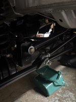
Some data first, the length from link pivot bolt to bottom bolt at axle is 32". The top bolt at axle is inclined about 4 degree towards aft of vehicle (the second pic is a bit deceptive due to shot angle)

IMG_3147.jpg
IMG_3145.jpg
IMG_3146.jpg
 

Yeller

Contributor
Bronco Guru
Joined
Mar 27, 2012
Messages
6,876
Loc.
Rogers County Oklahoma
Your schedule sounds as much fun as mine LOL

When you return, what is the distance from the floor to the center of the bolt at the frame, and the same at the axle? how far apart are the upper and lower bolt on the axle. It does have some nice looking fab work with robust parts.
 

ntsqd

heratic car camper
Joined
Jan 30, 2005
Messages
3,910
Loc.
Upper SoKA
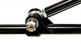
For the tie-rod clamp, while not as sexy as ntsqd's fully machined unit would be........

For the record, I modeled it fast and that makes it look machined, but I fully expected it to be fabricated. Those fillets represent welds, not cutting tool radii. The only reason for the stops was to not loose the axial location when the toe was being adjusted and the clamp was loose. While they could back-stop any slippage, that was not their original intent nor do I think that they'd ever be needed for that.
 

Yeller

Contributor
Bronco Guru
Joined
Mar 27, 2012
Messages
6,876
Loc.
Rogers County Oklahoma
Thanks for info, looks like an elegant approach to help reduce the roll. Seems like the Ford T-style used thru 1975 (before they when to the Y linkage) would have a similar roll issue as Jeeps that this part was designed for?
yes that would be it exactly. Jeeps are worse than bronco's/F150's. Jeeps drag link is inserted horizontal to the ground causing it to roll the tierod back and forth from the pressure from the drag link. Ford has them on a 45 degree upward slant so the drag link pushes/pulls inline with the tie rod reducing its tendency to roll the tierod. The Jeep system sucks and induces slop in the back and forth motion of the steering wheel.
 

toddz69

Sponsor/Vendor
Bronco Guru
Joined
Nov 28, 2001
Messages
10,556
yes that would be it exactly. Jeeps are worse than bronco's/F150's. Jeeps drag link is inserted horizontal to the ground causing it to roll the tierod back and forth from the pressure from the drag link. Ford has them on a 45 degree upward slant so the drag link pushes/pulls inline with the tie rod reducing its tendency to roll the tierod. The Jeep system sucks and induces slop in the back and forth motion of the steering wheel.
Yeah, the 45 degree angle of the Ford bits is one reason I run the shortened F150 tie rod setup on mine. I don't seem to have the drag link roll like the Chevy or Jeep parts do.

Todd Z.
 

toddz69

Sponsor/Vendor
Bronco Guru
Joined
Nov 28, 2001
Messages
10,556
Slept on this one a bit, could I get feedback on some of my thinking.

1) A stock Bronco radius arm setup tends to acts as a sway bar, correct due to "twisting" and generated reaction causing a force that tends to reduce body roll?

Yes.
3) An wristed link configuration loses much if not all of that benefit, but has more flex for off-road?

Correct. And you can see some dip on the side with the wristed arm under hard braking because the braking torque is no longer transferred to the frame.

4) If item 1 is correct, why did Ford add ant-sway bars in maybe 1976 years?
I have a theory on this, and no one has come up with a better answer, so I'm still sticking with it :). Ford changed the geometry on the front end in '76 due to not only the inverted-Y/Haltenberger linkage but they also changed the trac bar height relative to the frame - they lowered it with a longer bracket coming down off the frame. If you look at the 76-77 trucks head-on, the drag link (the long one) and the trac bar are in the same plane. So that means the handling is more neutral - 66-75 truck front ends were designed for understeer. Since the trac bar is lower, the roll moment couple between the roll center/center of gravity is larger, which theoretically makes the trucks slightly more tippy. My theory is that Ford added the sway bars because of the changes in the front end geometry to gain back some of the "losses" with the revised geometry and to make them handle a little better in general.

Todd Z.
 

Yeller

Contributor
Bronco Guru
Joined
Mar 27, 2012
Messages
6,876
Loc.
Rogers County Oklahoma
I have a theory on this, and no one has come up with a better answer, so I'm still sticking with it :). Ford changed the geometry on the front end in '76 due to not only the inverted-Y/Haltenberger linkage but they also changed the trac bar height relative to the frame - they lowered it with a longer bracket coming down off the frame. If you look at the 76-77 trucks head-on, the drag link (the long one) and the trac bar are in the same plane. So that means the handling is more neutral - 66-75 truck front ends were designed for understeer. Since the trac bar is lower, the roll moment couple between the roll center/center of gravity is larger, which theoretically makes the trucks slightly more tippy. My theory is that Ford added the sway bars because of the changes in the front end geometry to gain back some of the "losses" with the revised geometry and to make them handle a little better in general.

Todd Z.
We’ve discussed this before and are on the same page.

My brain despises understeer, so I tend to prefer a rear sway bar over a front one. Understeer has no in motion correction other than to slow down, which is most people’s natural reaction to things going wrong and perfect for the masses. However with my back ground, oversteer is desirable for handling traits, more throttle and steering out of the turn are the correction, a rear sway bar makes that possible.

Yeah, the 45 degree angle of the Ford bits is one reason I run the shortened F150 tie rod setup on mine. I don't seem to have the drag link roll like the Chevy or Jeep parts do.

Todd Z.
I have since done the same on the J truck, it also lengthened the drag link 4” which was needed. Didn’t hurt that a 78/79 tie rod was a direct fit. I do still run The Cure as well.
 
OP
OP
K

ksagis

Contributor
Aspiring Bronco Guru
Joined
Jun 15, 2020
Messages
386
yes that would be it exactly. Jeeps are worse than bronco's/F150's. Jeeps drag link is inserted horizontal to the ground causing it to roll the tierod back and forth from the pressure from the drag link. Ford has them on a 45 degree upward slant so the drag link pushes/pulls inline with the tie rod reducing its tendency to roll the tierod. The Jeep system sucks and induces slop in the back and forth motion of the steering wheel.
Sitting at airport with a bevy in hand and noodling.

I still like the idea of extending track bar to match lengths as the preferred approach for my next step, but had an idea that I could use feedback on.

To avoid the roll tendency on the tie rod linkage with a drag link attached to the tie rod, why not attach the drag link on top of tie rod instead of on front of tie rod linkage? The only downside I can see if making sure there isn’t binding at full droop. Seems like one of the misalignment inserts with the heim would solve any binding. Seems like the bending introduced from the drag link is the same with the drag link attached on front side or on top of tie rod.

Am I missing something?
 
Last edited:

DirtDonk

Contributor
Bronco Guru
Joined
Nov 3, 2003
Messages
49,402
I think you’re pretty much nailed it. It’s a limiting of travel. And a catastrophic failure at that point potentially as well.
Putting it at a slightly downward angle, gives it quite a bit more safety leeway due to the ability of the ball joint to rotate instead of just rocking.
And rocking motion many of them do not have much travel. Wouldn’t be safe to design it that way, using higher offset rod ends, if down the road, somebody uses a standard rod end.
 

Yeller

Contributor
Bronco Guru
Joined
Mar 27, 2012
Messages
6,876
Loc.
Rogers County Oklahoma
You are on a good track, and it is worth exploring, and if I was staring at it in person probably would have already gone there. Your drag link is already several inches longer than stock, is currently packaged anb everything fits. There is no reason to not shorten the drag link, weld tabs to the tie rod, and bolt the tie rod just like the hydraulic ram is only tabs pointed up with the bolt horizontal. That will probably even clean up the out of parallel that you currently have. Worst case it takes some of both, lengthening the track bar and shortening the drag link. Yes both the drag link and tie rod need to be as long as possible, but at the same time they need to physically fit and package in a manner that works and steers correctly, at a cost and labor point that makes sense. Like I said before everything is a compromise, the trick is getting those compromises to all play nice together.

I stole this from Duff’s web site but something like this. binding is not an issue and between the drag link and the hydraulic ram twisting of the tie rod is not an issue, it will have enough connections to be stable enough.
 

Attachments

  • IMG_3986.jpeg
    IMG_3986.jpeg
    61.1 KB · Views: 17

EPB72

Contributor
Sr. Member
Joined
Jul 13, 2019
Messages
940
Loc.
Pleasant Hill, CA
Sitting at airport with a bevy in hand and noodling.

I still like the idea of extending track bar to match lengths as the preferred approach for my next step, but had an idea that I could use feedback on.

To avoid the roll tendency on the tie rod linkage with a drag link attached to the tie rod, why not attach the drag link on top of tie rod instead of on front of tie rod linkage? The only downside I can see if making sure there isn’t binding at full droop. Seems like one of the misalignment inserts with the heim would solve any binding. Seems like the bending introduced from the drag link is the same with the drag link attached on front side or on top of tie rod.

Am I missing something?
image.jpg Zero roll,,
 

ntsqd

heratic car camper
Joined
Jan 30, 2005
Messages
3,910
Loc.
Upper SoKA
I'm reminded of an aspect of desert racing lower rear link design. In those if the damper lower bolts are placed on or above the CL of the link then they tend to try to roll-over the link and some means is required to keep them from doing that. Usually that is a pair of urethane bushings with some distance between them at the frame mount end of the link.
If the bolts are placed below the CL then the force exerted by the dampers themselves holds the link in the proper alignment and both ends of the link can be attached with a simple SRE.

Those tabs on the top of the tie-rod are above the tie-rod's CL and there is a force component trying to roll-over the tie-rod. The steeper the drag-link's angle, the higher this force will be. That it reportedly doesn't roll-over only means that the force trying to do it isn't large enough to make it happen, not that it isn't trying to.
 
Top