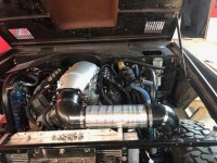
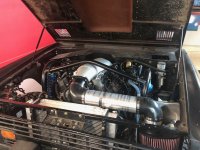
• Welcome to ClassicBroncos! - You are currently viewing the forums as a GUEST. To take advantage of all the site features, please take a moment to register. It's fast, simple and absolutely free. So please join our community today!
    If you have problems registering or can't log into your account, please contact Admin.

Cheaper Than Therapy: A Build Thread

OP
OP
M

marjama

Contributor
Sr. Member
Joined
Nov 24, 2004
Messages
451
Looking good Marcus!

Clearance issues are always a factor when doing mod's as we all know right!!?? :)

Gotta ask this one... how about clearance btw your TB & radiator & shroud? It was super tight for me & I wasn't running your manifold that brings it all even closer to your rad & fan.

Keep at it !!! :)

Don't you think I have enough problems to solve already, Brian?! Ha...I'm currently late to work because I was holding the throttle body up there with the radiator in place and trying to solve that. It's certainly solvable, but...it's definitely tight! I know others have done it. I'll work on that along with the engine and trans mounting this weekend. Stay tuned!
 
OP
OP
M

marjama

Contributor
Sr. Member
Joined
Nov 24, 2004
Messages
451
I definitely laughed out loud after I assembled a few more parts onto the Bronco this morning - this is clearly not going to work! :ROFLMAO:

PXL_20250426_130710831.jpg


Yes, the fan is currently inside the throttle body. Apparently the Holley Hi-Ram isn't intended to work with a mechanical fan! There are definitely some solutions to this (like, a sheet metal upper for the Hi-Ram, or maybe even cutting and welding the casting to reorient the throttle body), but for now...I'm going to think on it, and worry about other stuff.

Some super positive news - it turns out I wasn't running an Explorer water pump, and I just picked up 1/2" of extra clearance between the fan clutch and the radiator! I should have thought of this, but I was running the front cover and pump from a ~'92 Thunderbird 5.0, and that pump is slightly different. Pic attached of Flowkooler 1666 (the Explorer pump) vs the original T-bird unit. This also makes me laugh a bit - I've been re-reading my own build thread and ran across post #64 and #72 where I was struggling with this and managed to find the shortest of all the Explorer fan clutches. I spent so much time trying to save a few millimeters...and I was working with the wrong parts! Ugh! :LOL:

Alright...off to rebuild the trans mount (and do some F100 work). Hope you are all having a good weekend!
 

Attachments

  • PXL_20250424_171355379.jpg
    PXL_20250424_171355379.jpg
    141.4 KB · Views: 97

nvrstuk

Contributor
Just a Bronco driver for over 50 yrs!
Joined
Jul 31, 2001
Messages
10,605
Loc.
PNW
Check out the Super Vic if you can't move the engine back enough &/or move the fan & rad enough.
 

rcmbronc

Contributor
Bronco Guru
Joined
Dec 15, 2003
Messages
2,778
Loc.
Tomah WI
I know when I had that intake I had to lower the radiator a bit.,
 

Attachments

  • IMG_5582.JPG
    IMG_5582.JPG
    206 KB · Views: 93
  • IMG_5596.JPG
    IMG_5596.JPG
    211.9 KB · Views: 103
  • IMG_5597.JPG
    IMG_5597.JPG
    231.5 KB · Views: 84
  • IMG_5598.JPG
    IMG_5598.JPG
    170.8 KB · Views: 85
  • IMG_5653.JPG
    IMG_5653.JPG
    197.3 KB · Views: 102
OP
OP
M

marjama

Contributor
Sr. Member
Joined
Nov 24, 2004
Messages
451
I know when I had that intake I had to lower the radiator a bit.,
Thanks @rcmbronc! I remembered you had done it - those pics are super helpful! I was digging around the other day trying to find photos of your setup. If I remember right, you were running a 351w based block, so also a bit taller?

It's pretty clear that an electric fan is required if I want this to work without other really significant modifications. I'm working on a couple of options at the moment. I picked up a second 'scratch and dent' upper lid from Holley with the idea that I will cut and weld the throttle body attachment to make it work with the mechanical fan. (Figured it was best to have a backup just in case I scrap the parts and the plan!) Plan B is to drop the radiator down a bit more, and move it forward. Your tube structure looks like it pushes the radiator forward a bit more than my current setup.

The tape roll in the image below is ~4.375" OD, and the hood is resting a bit lower than it will once the hood latch is back in place, so there is room to pull this off if the throttle body is up much closer to the intake.

PXL_20250427_183219755.jpg
 
OP
OP
M

marjama

Contributor
Sr. Member
Joined
Nov 24, 2004
Messages
451
I spent a bit of time staring at things...then proceeded to roll the dice and went to town cutting stuff up. The manifold modifications are definitely not something I'm confident in, but worst case I'm scrapping a $250 manifold top (I did buy the backup, afterall), and will learn something! I spent a ridiculous amount of time staring at things, taking measurements, and then finding a way to semi accurately mark the part for cutting. I'm changing the angle from 25° to 10° and lopping off enough to give myself room to get a ø4" elbow in there. Maybe. The first two pics show the setup, the third is when things got serious! Below pic is where I'm at now. Next step is to design a new throttle body adapter...going to require some blending to make it all work out!

PXL_20250504_200931142.jpg
 

Attachments

  • PXL_20250504_200515671.jpg
    PXL_20250504_200515671.jpg
    226 KB · Views: 102
  • PXL_20250504_045050605.jpg
    PXL_20250504_045050605.jpg
    197.9 KB · Views: 75
  • PXL_20250503_043712080.jpg
    PXL_20250503_043712080.jpg
    183.6 KB · Views: 113

nvrstuk

Contributor
Just a Bronco driver for over 50 yrs!
Joined
Jul 31, 2001
Messages
10,605
Loc.
PNW
Looks like a good start Marcus!

Hardest part for all of us is that first cut huh? Always is! :)
 
OP
OP
M

marjama

Contributor
Sr. Member
Joined
Nov 24, 2004
Messages
451
Looks like a good start Marcus!

Hardest part for all of us is that first cut huh? Always is! :)

You've got that right, Brian! Nothing like chopping up a perfectly good component without knowing if intended modifications are even going to work! It's only slightly easier when I have a backup part :)

Went ahead and cut a brand new Moroso oil pain while I was at it. Might as well keep cutting while I'm feeling brave! Had to make clearance at the front sump (this is also partly why I'm using a standard non-hv oil pump - both based on general recommendation, and it's shorter). Still a bit more clearance checking to do before I weld it back up, but I really need to acquire a second floor jack to accomplish this. Man, quality floor jacks have gone up in price!

Found out today that just before full droop the front driveshaft binds up. Well, it's technically not the front shaft - it's the rear that Tom Wood's made for me. I installed it on the front to help with checking clearances since the front and rear shafts were the same length before. Funny, with the change to the 4R70W and the addition of the short output on the Atlas TC, they are still effectively the same length (and the new driveshaft is not quite correct for either one!). Will have to address this issue later.

Installed the Winter's shift arm today temporarily to aid in checking clearances. The pan has clearly never been off the trans that I picked up (plastic dip stick seal-thingy was still in the pan). I'm curious to see that some/most people who are running a 4R70W with a Sidewinder shifter seem to be using the Lokar shift arm instead. I'm curious if this is necessary, or if the Winters supplied one will work. I'm definitely going to need a smaller diameter front shaft as well.
 

Attachments

  • PXL_20250504_001406510.jpg
    PXL_20250504_001406510.jpg
    206.2 KB · Views: 98
  • PXL_20250503_223512500.jpg
    PXL_20250503_223512500.jpg
    182.2 KB · Views: 76
  • PXL_20250503_224426511.jpg
    PXL_20250503_224426511.jpg
    225.1 KB · Views: 87
  • PXL_20250503_225044566.jpg
    PXL_20250503_225044566.jpg
    194.3 KB · Views: 106
Last edited:

nvrstuk

Contributor
Just a Bronco driver for over 50 yrs!
Joined
Jul 31, 2001
Messages
10,605
Loc.
PNW
Keep cutting while you can still fathom the audacity to cut up BRAND NEW parts! :)

Back around 2010 I used the Winters supplied arm. However, I did move the connection to the Winters cable to be directly under the pan rail for DS clearance. Mod the attachment brkt at the back of the pan also.

I did something similar on my 6r shifter cable but ended up changing & coming from in frt of the bellhousing & over the top of my bellhousing for clearance.

Keep up the great work!
 
Last edited:
OP
OP
M

marjama

Contributor
Sr. Member
Joined
Nov 24, 2004
Messages
451
Well, nothing too exciting here - but I'm still making baby steps forward, which is more than I can say for the last year+!

I managed to dismantle the cross member that I built for the 700R4, and reconfigured it for the 4R70W. I'm using Energy Suspension P/N 4.1136G for the transmission mount, machined an aluminum spacer and few plates that became a new mounting plate. Everything is just tacked together for now, which can be said about most of the truck at this point. I couldn't find a 1.75" hole saw in my shop to save my life (except one that was missing half the teeth!). So, I did it the slow and accurate way and used the mill to cope the plates for the tube.

I spent quite a bit of time contemplating clocking the transfer case back down a bit, but in the end settled with retaining the high location. I'm definitely going to deal with binding at full droop with a stock 1350 CV, so may need to limit travel at the diff. It also has quite a bit of plunge (TBD on exactly how much). The Tom Woods driveshaft that I had for the rear definitely didn't have enough spline travel to work in the front. (Both front and rear driveshafts are within 1/4" in static length - handy!) So, more problems to solve...later!

Next up is either machining the flange for the throttle body, or getting to work on the new engine mounts to solve link clearance issues.
 

Attachments

  • PXL_20250511_040911397.jpg
    PXL_20250511_040911397.jpg
    160.6 KB · Views: 122
  • PXL_20250515_045438118.jpg
    PXL_20250515_045438118.jpg
    175.2 KB · Views: 104
  • PXL_20250515_045432219.jpg
    PXL_20250515_045432219.jpg
    205.7 KB · Views: 134
Last edited:
OP
OP
M

marjama

Contributor
Sr. Member
Joined
Nov 24, 2004
Messages
451
A bit more progress over the last couple of weeks - clearly I'm out of practice on taking pics to document the build (especially while machining), because I keep just moving ahead only to later realize that I never took any photos! The throttle body is mounted and there should now be plenty of clearance for intake plumbing with (modified) Holley Hi Ram!

There were a lot of steps to get to this point, along with plenty of over-thinking. I would not consider myself an aluminum welder, but things turned out OK. After lopping the front of the intake off (see post #307 above), I spent a good bit of time modeling a new flange and printing plastic prototypes - I think I made around 8 or 9. I programmed the part and ended up making a pair on the CNC mill, then used the cut off part to practice welding and test out the idea. That went fine and really helped me get comfortable with moving forward on the final intake. I was worried about welding the casting, and also about warping the part...neither turned out to be an issue.

Attached are a handful of pics of the progression along with the final result. One more problem solved! I still need to blend the internal surfaces, and may smooth out the welds in an attempt to make it look like it is just a casting, but that is really low on the list of things to do at the moment! My only potential worry is that the intake tubing could come in contact with the scoop, but I think I should be able to clear it. Any suggestions on what filter to run for this setup? The air box will likely go on the drivers side to avoid conflict with radiator hoses, but TBD.
 

Attachments

  • PXL_20250526_185138785.jpg
    PXL_20250526_185138785.jpg
    112.4 KB · Views: 106
  • PXL_20250526_184745318.jpg
    PXL_20250526_184745318.jpg
    218.6 KB · Views: 120
  • PXL_20250526_184254654.jpg
    PXL_20250526_184254654.jpg
    178.6 KB · Views: 116
  • PXL_20250526_184248619.jpg
    PXL_20250526_184248619.jpg
    209.5 KB · Views: 122
  • PXL_20250519_034403403.jpg
    PXL_20250519_034403403.jpg
    256 KB · Views: 136
  • PXL_20250527_021917272.jpg
    PXL_20250527_021917272.jpg
    247.8 KB · Views: 133
  • PXL_20250505_010116428.jpg
    PXL_20250505_010116428.jpg
    154.1 KB · Views: 98

nvrstuk

Contributor
Just a Bronco driver for over 50 yrs!
Joined
Jul 31, 2001
Messages
10,605
Loc.
PNW
NO filter recommendations but run an OuterWears or equiv prefilter to keep the water and crap out.
 
OP
OP
M

marjama

Contributor
Sr. Member
Joined
Nov 24, 2004
Messages
451
Well, I finally had a big block of free time over the weekend, and got to work on getting the engine attached to the frame. With 6" of up travel and the axle moved forward, there are plenty of things that want to be in the same place at the same time - and the engine mounts had to change. So, out came the engine and off came the old mounts. I'm reusing the bushings from the "extreme mounts" that I was using before, and fabricated everything else. (Now that I'm typing this...I realize that I didn't post up anything about the oil pan mods required for clearance!)

I used some 1.75" DOM to create a longer mount, and machined a center pin to fit. A combination of 1/4" and 3/16" plate for the rest of the mount construction. I had been stuck on this part of the project because I no longer have access to the press brake at work (since that company went out of business...and I didn't buy the press brake), but I ran across some bent 1/4" plate in my material stash that would work great for the frame mount and modified them to fit. These will bolt to a nut plate that will be inside the frame when this is complete. Then I spent way too much time with some more 1.75" DOM tube to connect the frame to the engine mounts. It's now finally self supporting again (and level within 0.5°...was kind of expecting worse)!

One thing I forgot about - the Boss blocks have screw in freeze plugs, and they definitely did not work with the original extreme mounts without a ton of grinding. I don't know what mounts Ford intends for people to use, but I don't believe the off the shelf stock mounts work either.

The rest of the pics are just to show how tight things get when you attempt to have a 3 link front suspension + 6" up travel. The air bumps will be set to never let it get quite this close, but...it's really tight! Once things are locked in I will need to get the air bumps back in and articulate everything to double check that nothing was missed.
 

Attachments

  • PXL_20250825_035050019.jpg
    PXL_20250825_035050019.jpg
    122.1 KB · Views: 118
  • PXL_20250825_034842173.jpg
    PXL_20250825_034842173.jpg
    136.1 KB · Views: 112
  • PXL_20250825_033416661.jpg
    PXL_20250825_033416661.jpg
    175.3 KB · Views: 89
  • PXL_20250825_033408503.jpg
    PXL_20250825_033408503.jpg
    224.4 KB · Views: 111
  • PXL_20250824_024631516.jpg
    PXL_20250824_024631516.jpg
    189.7 KB · Views: 65
  • PXL_20250802_221835827.jpg
    PXL_20250802_221835827.jpg
    200.4 KB · Views: 101
  • PXL_20250623_032926727.jpg
    PXL_20250623_032926727.jpg
    220.9 KB · Views: 102

nvrstuk

Contributor
Just a Bronco driver for over 50 yrs!
Joined
Jul 31, 2001
Messages
10,605
Loc.
PNW
Gotta feel GREAT to get a weekend of work in!

TIGHT is the word when trying for that extra 1" to 1 1/2" of uptravel. Wait till the hydro assist cyl needs a home! lol

I totally understand the fruatration with anybody else that worked for 2 extra months for an inch! lol. Crazy, that's a good description! :)
Primaries look almost 1 7/8"??
 
OP
OP
M

marjama

Contributor
Sr. Member
Joined
Nov 24, 2004
Messages
451
Ha, man Brian...I don't want to think about the parts I haven't even thought about yet (like hydro assist)! I'm just trying to keep the Bronco creeping along. I have this idea of "do something every day, even if it is small" - the silly part is, I'm trying to doing that on three projects and I'm usually successful on one or two. It's definitely satisfying to feel like I finished something significant.

The primaries on the header starts are 1 3/4". Those are from Stainless Headers, and the flanges and starts seem like good products. I ordered some of their formed collectors, and can't recommend them. The fit was ridiculously bad (see pics). Maybe someone who is much more patient and/or a better fabricator than I am would have had no issues, but I sent them back (on my own dime even). I have three stainless exhausts to build, but the Bronco headers seems like they might be the biggest challenge. I designed and 3D printed a bunch of 'iceworks' style modeling blocks, which will hopefully make me a bit more successful! I'm still trying to decide on the collector size and if I'm going to make a venturi style exit or not for these headers - I'm sure some math exists out there, but I haven't dug it up yet. Headers will exit outside the frame, fenderwell style. This is another problem for a future post though :)
 

Attachments

  • PXL_20250617_130611960 (2).jpg
    PXL_20250617_130611960 (2).jpg
    110.7 KB · Views: 95
  • PXL_20250617_130428037 (2).jpg
    PXL_20250617_130428037 (2).jpg
    247.2 KB · Views: 88
Last edited:

nvrstuk

Contributor
Just a Bronco driver for over 50 yrs!
Joined
Jul 31, 2001
Messages
10,605
Loc.
PNW
Sounds like you've got a good work. Ethic that you're trying to keep at it even with family and all those other issues that we all know, get in the way, almost every day, lol. ;)

Hang in there it's looking great.

I have tried to get a couple of header companies to make shortage that x out over the frame rail, just in the behind the engine block. They are either too busy pumping out stuff.
That they already make, or they want a little bit more than a small fortune... i want to build a different set for mine also... But i'm not doing that until I figure out what permanent changes I'm going to make.
 

ntsqd

heratic car camper
Joined
Jan 30, 2005
Messages
5,953
Loc.
Upper SoKA
FWIW The advice that a desert race fab guy gave to a good friend of mine is to not use a hydro-bump as the final up-travel limit. Use a preferably rubber trad bump-stop as the actual final limit. Maybe that's dated advice, but at the time running a hydro-bump clear to zero had been proven to be a bad idea.

Just in case stupid money is no object: https://burnsstainless.com/products/4-into-1-base-collectors?variant=8774780813403
The math does exist to calculate what that reduced diameter should be, where it should be, and what the rate of taper should be. I don't know what it is, but I used to know a welder who had a Master's in math (lost track of him when he retired). He WAS the Coyote's arse to a Palm Tree kind of welder and did all of those calcs for me on a college project. That one was simple compared to the expansion chamber that he made for a nitro burning Vespa 2-smoker!
It was also he who put me onto this firm: https://coneeng.com/

FWIW I've taken to building exhaust couplings like this:
i-c3jtppb.jpg

Lately I've been having SendCutSend or OSHCut cut the flanges out for me in 304 SS. The downstream flange's ID fits over the expanded piece of tubing and opening up the purchased flanges is a spooky lathe set-up and it takes a while. Much easier to just order them already the right ID. A small bead of high temp silicon is the most that is needed to get it to seal.
[EDIT] I failed to mention that this isn't my design. OG's will recognize "MISF", it is his original design. [/EDIT]
 
Last edited:
OP
OP
M

marjama

Contributor
Sr. Member
Joined
Nov 24, 2004
Messages
451
Sounds like you've got a good work. Ethic that you're trying to keep at it even with family and all those other issues that we all know, get in the way, almost every day, lol. ;)

Hang in there it's looking great.

I have tried to get a couple of header companies to make shortage that x out over the frame rail, just in the behind the engine block. They are either too busy pumping out stuff.
That they already make, or they want a little bit more than a small fortune... i want to build a different set for mine also... But i'm not doing that until I figure out what permanent changes I'm going to make.

Is any change really all that permanent? :) I'm going to take a stab at making my own, and I suspect it'll cost a small fortune...but much less than having someone else make me a set of custom stainless headers. I've been staring at the body mount and lift block I have in there currently and trying to decide exactly where I want to exit - I may cut off the factory mount, eliminate the lift block, and free up some additional room there to pass by. I don't really like the idea of sneaking a hot exhaust tube in between and going really close to the floor pans.

I'd volunteer to make you a set of custom headers, but we all know that would probably take 12 years!

FWIW The advice that a desert race fab guy gave to a good friend of mine is to not use a hydro-bump as the final up-travel limit. Use a preferably rubber trad bump-stop as the actual final limit. Maybe that's dated advice, but at the time running a hydro-bump clear to zero had been proven to be a bad idea.

Interesting - I'm planning on using the hydro bump as the final up travel limit in normal travel. I don't recall us (Fox) ever telling customers to not use them that way as long as they are set up properly, but I suppose I could see them getting pushed up into the mount on a hard hit in a desert application. I am pretty sure I won't be jumping the Bronco, so I'm not sweating it at the moment. Using the shock as a final bottom out is a well know no-no (and a good way to tear off suspension components), but it's mostly impossible to do that with really high articulation with the current setup.

Just in case stupid money is no object: https://burnsstainless.com/products/4-into-1-base-collectors?variant=8774780813403
The math does exist to calculate what that reduced diameter should be, where it should be, and what the rate of taper should be. I don't know what it is, but I used to know a welder who had a Master's in math (lost track of him when he retired). He WAS the Coyote's arse to a Palm Tree kind of welder and did all of those calcs for me on a college project. That one was simple compared to the expansion chamber that he made for a nitro burning Vespa 2-smoker!
It was also he who put me onto this firm: https://coneeng.com/

I wish money was no object...but I haven't quite reached that stage of life just yet! I've been on the cone engineering site quite a bit. Just need to free up some time to dig up the equations and do some math! I remember buying a 2 stroke pipe design book many years ago when I was racing karts. That was some DRY reading! Needless to say, I never built my own pipe :)

FWIW I've taken to building exhaust couplings like this:
i-c3jtppb.jpg

Lately I've been having SendCutSend or OSHCut cut the flanges out for me in 304 SS. The downstream flange's ID fits over the expanded piece of tubing and opening up the purchased flanges is a spooky lathe set-up and it takes a while. Much easier to just order them already the right ID. A small bead of high temp silicon is the most that is needed to get it to seal.

I dig it - that's compact! I was eyeballing some ball and cup style couplings similar to what is stock on my Cayenne diesel, but it's hard to find much that is readily available other than v-bands.
 
Top