• Welcome to ClassicBroncos! - You are currently viewing the forums as a GUEST. To take advantage of all the site features, please take a moment to register. It's fast, simple and absolutely free. So please join our community today!
    If you have problems registering or can't log into your account, please contact Admin.

James Duff Long Arm Install questions

staleb00

Contributor
New Member
Joined
Apr 19, 2025
Messages
26
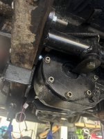
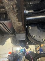
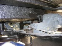
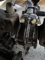
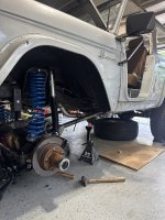
Trying to install these duff long arms I got from a fellow bronco owner. They are an older model based on the shock attachment but have a couple questions. They came with spacers but I was told not to use them. I got the c caps on with some serious work. But my c bushings are busting out the seams. Doesn’t feel right so any guidance on that would help appreciate. Front axle is its original Dana 44.

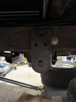
Second issue is that my bracket mount for the arms are running into where my transfer case bracket is. Instructions say I need to center at 10.25 inches from previous stock arm bracket bolt. From looks of it. I’ll be about .5 inches too short from getting there. If i go 9.75 off center from the bolt on both sides, will that impact anything?
 

Attachments

  • IMG_9758.jpeg
    IMG_9758.jpeg
    151.3 KB · Views: 184
  • IMG_9759.jpeg
    IMG_9759.jpeg
    123.4 KB · Views: 157

SLOWnEASY

Contributor
Sr. Member
Joined
Sep 26, 2022
Messages
517
Loc.
San Diego, Ca.
I think my new C cup bushings bulge out about the same as your picture. But just asking. Did you pay attention to the inner markings of each bushing that identifies if it is a front or rear top or bottom?
 

jamesroney

Contributor
Bronco Guru
Joined
Sep 11, 2007
Messages
2,594
Loc.
Fremont, CA
Second issue is that my bracket mount for the arms are running into where my transfer case bracket is. Instructions say I need to center at 10.25 inches from previous stock arm bracket bolt. From looks of it. I’ll be about .5 inches too short from getting there. If i go 9.75 off center from the bolt on both sides, will that impact anything?
You want to follow the instructions, and you either need to put the bracket where they tell you, or else you'll need to shorten the arms.

The clearance between the factory tie rod and the pitman arm is very tight. .5 inches is huge. Bigger tie rod ends and high steer make it more obvious. If you end up running a shorter pitman arm for clearance, you will reduce your turning radius.

Funny that you said "impact." Indeed, at full suspension stuff...the tie rod will "impact" the pitman arm, and drive the sector out the top of the steering box. The good news is that the pitman arm keeps it from going thru the hood. It makes a huge mess, but it's very easy to detect.
 
OP
OP
staleb00

staleb00

Contributor
New Member
Joined
Apr 19, 2025
Messages
26
I think my new C cup bushings bulge out about the same as your picture. But just asking. Did you pay attention to the inner markings of each bushing that identifies if it is a front or rear top or bottom?
Yea. Double checked it on both sides. Was the first thing I did after seeing it.
 
OP
OP
staleb00

staleb00

Contributor
New Member
Joined
Apr 19, 2025
Messages
26
You want to follow the instructions, and you either need to put the bracket where they tell you, or else you'll need to shorten the arms.

The clearance between the factory tie rod and the pitman arm is very tight. .5 inches is huge. Bigger tie rod ends and high steer make it more obvious. If you end up running a shorter pitman arm for clearance, you will reduce your turning radius.

Funny that you said "impact." Indeed, at full suspension stuff...the tie rod will "impact" the pitman arm, and drive the sector out the top of the steering box. The good news is that the pitman arm keeps it from going thru the hood. It makes a huge mess, but it's very easy to detect.
Makes sense on the tie rod and pitman arm, and honestly didn’t even consider that. Just assumed the axle would sit .5 inches forward or I could accommodate the shorter distance by shortening the arms at the heim joint bolt. Guess I’ll need to figure out a way to dry fit it all with out actually drilling or welding the brackets in place (thankfully I haven’t cut the factory bracket yet either) to see where everything lines up.
 

DirtDonk

Contributor
Bronco Guru
Joined
Nov 3, 2003
Messages
51,613
What transfer case bracket? The angled supports that the crossmember sits on? Got a different pic? Or maybe it’s just my small screen (and dim eyes!) not letting me see it?
What is that new-ish looking bolt doing there?
Seems like the only stock item that would be in the way would be the old radius arm bracket. Which you’re saying you have not removed yet?
Or do you have a Ford NP205 with side support?

On the bushings squeezing out like that, it’s not “right” but it is becoming more normal.
Lots of possible reasons, but the bottom line is that it doesn’t hurt anything.
Looks ugly as heck🙄, but they still do their job.
 
OP
OP
staleb00

staleb00

Contributor
New Member
Joined
Apr 19, 2025
Messages
26
What transfer case bracket? The angled supports that the crossmember sits on? Got a different pic? Or maybe it’s just my small screen (and dim eyes!) not letting me see it?
What is that new-ish looking bolt doing there?
Seems like the only stock item that would be in the way would be the old radius arm bracket. Which you’re saying you have not removed yet?
Or do you have a Ford NP205 with side support?

On the bushings squeezing out like that, it’s not “right” but it is becoming more normal.
Lots of possible reasons, but the bottom line is that it doesn’t hurt anything.
Looks ugly as heck🙄, but they still do their job.
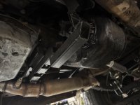
Yea, not my best explanation and calling things by their exact name is also a not a strong area of mine. It’s the transfer case cross member that’s the issue. Those bolts are to secure it to the frame. See the pic. It’s an np205 that the PO installed I believe.

Called Duff and they recommended I grind down the “mounts”/side supports for the TC membrane to make it work…not sure I want to take apart this thing any more. So might try and see what happens by shaving their arm brackets a bit and threading the rod ends as far as they’ll go.

Got it on the c bushings. As long as it does its job is all I care about. I guess my next question though would be what would happen if I just kept the spacers on?
 

Attachments

  • IMG_9776.jpeg
    IMG_9776.jpeg
    206.2 KB · Views: 154
  • IMG_9780.jpeg
    IMG_9780.jpeg
    168.5 KB · Views: 145

ntsqd

heratic car camper
Joined
Jan 30, 2005
Messages
5,953
Loc.
Upper SoKA
Put the bracket where the instructions say to put it. As James said above, any other location forces compromises that you don't want to make.

Can we get a wider angle shot of the cross-member? Any idea who made it? I tried looking it up and got nowhere. If is built the way that I fear it was it's a bad design and should be changed regardless.
 

DirtDonk

Contributor
Bronco Guru
Joined
Nov 3, 2003
Messages
51,613
Got it on the c bushings. As long as it does its job is all I care about.
Yeah, it’s been a pain for a few years now. But so far nobody’s had any real trouble other than the look.
It is distorting the bushings, but doesn’t seem to be hurting their castor correction factor any.

Did the caps come with the arms? If so, then they are probably clean and free of rust.
If they are for the original radius arms, then they can probably benefit from some scraping and grinding/cleaning.
Same for the pads/plates that are welded to the axle itself. They build up rust, and have scale from the factory sometimes.
Any additional material, even a few thousandths worth, will cause the bushings to squeeze out more. A surprising amount, in fact!
So a good practice when installing C-bushings is to make sure that the surfaces are clean and ground smooth, and use a lubricant specifically designed for polyurethane.
Or liquid hand soap!
I guess my next question though would be what would happen if I just kept the spacers on?
Sorry, I must’ve missed it. What spacers?
 

DirtDonk

Contributor
Bronco Guru
Joined
Nov 3, 2003
Messages
51,613
Obviously, you’re dealing with two sets of non-stock parts, trying to fit in the same space.
Where neither company knew what the other one was gonna be doing, or what you were eventually going to be adding to the vehicle.
So yeah, it falls entirely on you to make them both play nice together.

If it was more than that half inch that you’re talking about, I would just temporarily remove the transfer case bolt, install the new radius arm bracket, drill a hole through it and run a new longer bolt (if needed) back to the transfer case support.
That, or just notch the new bracket because half inch isn’t that much.
But like they said, you still want them where they’re supposed to be.

We’ll find out more details about what’s wrong with the transfer case mount I hope.😉😁
So more pics please.
What’s up ntsqd?
 

ntsqd

heratic car camper
Joined
Jan 30, 2005
Messages
5,953
Loc.
Upper SoKA
Generally 4 mounting points for the power-train is a bad idea. 3 mounts is much better. The OEM EB mount design, even though it is technically 4 mounts, can be considered to be a 3 point system due to how close together the two trans-t/c mounts are. In some cases 4 points actually makes the frame more rigid, but usually what it does is put stress on things like the trans to t/c adapter or the bell-housing (particularly the die-cast auto trans b/h's) that they're not designed for. There are exceptions where it has been done and it works, but it's generally a bad idea unless you've got a lot of time and money to engineer it to work.
For instance, early D18 t/c's have a little foot for a fourth mount under the front output yoke. I've never seen one in a vehicle that was used as intended that wasn't broken.

Goes back to high school geometry class. Three points define a plane. The fourth point will not always be on that plane. When it isn't it is putting stress on everything else.
 
OP
OP
staleb00

staleb00

Contributor
New Member
Joined
Apr 19, 2025
Messages
26
Generally 4 mounting points for the power-train is a bad idea. 3 mounts is much better. The OEM EB mount design, even though it is technically 4 mounts, can be considered to be a 3 point system due to how close together the two trans-t/c mounts are. In some cases 4 points actually makes the frame more rigid, but usually what it does is put stress on things like the trans to t/c adapter or the bell-housing (particularly the die-cast auto trans b/h's) that they're not designed for. There are exceptions where it has been done and it works, but it's generally a bad idea unless you've got a lot of time and money to engineer it to work.
For instance, early D18 t/c's have a little foot for a fourth mount under the front output yoke. I've never seen one in a vehicle that was used as intended that wasn't broken.

Goes back to high school geometry class. Three points define a plane. The fourth point will not always be on that plane. When it isn't it is putting stress on everything else.
Attaching a couple photos to show what I got. I couldn’t tell you if this is good or bad. Just how I got it and why I’m trying to make it amy own. For better or worse. lol. Open to all the suggestions. The PO didn’t have it working for 4 wheel drive either, so that’s next on the list.
 

Attachments

  • image.jpg
    image.jpg
    118 KB · Views: 138
  • IMG_9790.jpeg
    IMG_9790.jpeg
    220 KB · Views: 154
  • IMG_9792.jpeg
    IMG_9792.jpeg
    260.6 KB · Views: 145

ntsqd

heratic car camper
Joined
Jan 30, 2005
Messages
5,953
Loc.
Upper SoKA
The bushing in the first pic is intended to control torque rather than supporting the rear of the trans & t/c as I had feared it might be. For now I think that you can remove that whole rear assembly without worry, although I'd leave that plate on the t/c for now - may be useful in the future. I think that eventually a better rear cross-member will need to be constructed as that one looks a bit scary to me. For ease of working on the front drive-shaft I would go over the top of the front output rather than under it as it is currently.

So, short version; remove that whole rear bushing assembly. Once that assembly is gone you can put the radius arm brackets where they're supposed to be.
 

Jetfixr320

Jr. Member
Joined
Jun 26, 2025
Messages
130
Attaching a couple photos to show what I got. I couldn’t tell you if this is good or bad. Just how I got it and why I’m trying to make it amy own. For better or worse. lol. Open to all the suggestions. The PO didn’t have it working for 4 wheel drive either, so that’s next on the list.
Your transfer case mount could easily be trimmed off and move the two forward mount holes back the required amount to let your long arm mounts attach correctly. That mount looks quite stout,
 
OP
OP
staleb00

staleb00

Contributor
New Member
Joined
Apr 19, 2025
Messages
26
As an update. Shaved backed the brackets a quarter inch and got everything lined up. However, can’t get the nuts on now bc of the NP205. Swear it’s one thing after another. Need to drop the transfer case, which is the last thing I want to do unless anyone has any recommendations.

If I do drop it, was thinking about going twin stick or just adding a normal shifter. PO only had the back driveshaft attached. Can’t tell what style though. Looking for any and all input on recommendations here…
 

Attachments

  • IMG_9840.jpeg
    IMG_9840.jpeg
    165.8 KB · Views: 112
  • IMG_9842.jpeg
    IMG_9842.jpeg
    227.2 KB · Views: 107

DirtDonk

Contributor
Bronco Guru
Joined
Nov 3, 2003
Messages
51,613
Not sure of the downsides or benefits, other than clearance, but what about creating a nut plate?
Quarter inch steel, or thicker if it’ll fit in there, thread it and hold it up there when you’re tightening the bolt. Use some Loctite.

Seems like the nut and locking nut would be better. But it’s a suggestion anyway.
 

bax

Contributor
Old Member
Joined
Aug 22, 2005
Messages
14,549
Ok I run the 205 in one of my broncos. It's real hard to fit it under the body without doing a 2'' body lift. The 205 should lifted up higher. Your front output angle is pointing up I would guess about 10 degrees. That makes it hard to get that front shaft to work even with a high angle shaft. I would make a new Case mount. You can put a mount on top of the frame. I see the body is already cut to clear the top of the transfer case. Telling me you are out of room. I dont know how much work you want to do but I bet I can find a few pictures that might help if you want to change things up.
 

bax

Contributor
Old Member
Joined
Aug 22, 2005
Messages
14,549
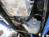
Here is a trans mount and a t case mount . This is with a 3'' body lift, but a 2'' is better. Just a few ideas.
 

Attachments

  • P1010003_7.JPG
    P1010003_7.JPG
    108.3 KB · Views: 123
  • P1010005_7.JPG
    P1010005_7.JPG
    108.6 KB · Views: 155
OP
OP
staleb00

staleb00

Contributor
New Member
Joined
Apr 19, 2025
Messages
26
I was planning on doing a 1 inch body lift bc I need to create some extra space in the engine bay (running a 97 explorer 5.0). Plan was to do the body lift this winter bc I actually want to drive this thing but sounds like I should go to 2? Problem is I keep going higher and this rig will primarily be a city driver.
 
OP
OP
staleb00

staleb00

Contributor
New Member
Joined
Apr 19, 2025
Messages
26
Here is a trans mount and a t case mount . This is with a 3'' body lift, but a 2'' is better. Just a few ideas.
Where did you get that trans mount from? And can you send a different angle of that t case mount?
 
Top