• Welcome to ClassicBroncos! - You are currently viewing the forums as a GUEST. To take advantage of all the site features, please take a moment to register. It's fast, simple and absolutely free. So please join our community today!
    If you have problems registering or can't log into your account, please contact Admin.

Alternator & VR problems

69bronco69

Full Member
Joined
Jul 9, 2011
Messages
190
Loc.
Central Arkansas
Back again with more problems:
Few days ago had a dead battery. Tested at 11.4 volts. Took it to NAPA - they said a bad cell. Put in new battery. Within a week - dead battery.
Here is what I did:
1. Cleaned battery terminals and posts
2. Charged battery and then test battery across post - got 12.4 volts
3. Started engine and tested bettery across post - got 12.4 volts = not charging
4. Turned off Engine and removed ground cables from battery
5. Used test light from negative post to ground - test light did not come on = no battery drain
6. Reattached battery cables
7. Unplugged VR and plugged it to temp replacement VR that was grounded to negative post of battery with jumper wire/alligator clips
8. Started engine and tested battery across post - got 12.4 volts
9. Followed same process with another VR and got same results.
10. removed battery cables and alternator - noticed broken wire from stud see pic:http://i1116.photobucket.com/albums/k561/j7o7h7n7/utf-8BSU1HMDAyNTktMjAxMTA3MjYtMTIwMS5qcGc.jpg
11. fixed wire and reinstalled alternator and battery cables.
12. Tested with old VR and the other two VR's and got same 12.4 volts reading with engine running
13. Installed used alternator and performed tests with the same three VR's and got same 12.4 volts reading
14. I did noticed there was some corrosion on the plug that goes into the VR after all the previous steps above. One of the wires broke off from the plug at the "A" that goes into the VR. It was yellow wire plugged into same terminal of another yellow wire. It goes to the "thing" that is supposed to keep the humm sound out of the AM radio i think.
VR broken wire - http://i1116.photobucket.com/albums/k561/j7o7h7n7/utf-8BdnIgYnJva2VuIHdpcmUuanBn.jpg

corroded plug - http://i1116.photobucket.com/albums/k561/j7o7h7n7/utf-8BdnIgcGx1Zy5qcGc.jpg

I borrowed the two VR's and alternator from local shade tree mechanic. He said they all worked when they were removed from other Fords.

I'm not sure how to use multimeter as to test which terminals on alternator or VR other than what I did above. I have read other threads but still dont quite get where to put the multimeter leads on which terminals to do the testing.

I thinking of getting a plug from junkyard ford to see if that is the culprit. Did I miss anything? Please Help

john
 

Viperwolf1

Contributor
electron whisperer
Joined
Aug 23, 2007
Messages
24,346
Links don't work.

You can take the alternator to a parts store and have it tested. The "thing" is not important for charging.
 
OP
OP
69bronco69

69bronco69

Full Member
Joined
Jul 9, 2011
Messages
190
Loc.
Central Arkansas
Links don't work.

You can take the alternator to a parts store and have it tested. The "thing" is not important for charging.

I think I found something that may help the other thread u were helping me with the coil getting hot with key on ACC.

I did a continuity test from the plug at the VR. The orange to alternator was ok and so was the yellow to stater selonoid. but the green with red was not. I did have continuity on green with red at the plug as it exits from firewall behind the fuse box on engine compartment side. On the plug from that point which is the pink wire toward the coil - no continuity. It has been cut and taped off.
On other thread, that is where that green wire was spliced into the pink wire coming from coil and ran to the big stud terminal on the back of ignition switch.

So, if I connect that pink wire back to coil should I:
1. have continuity to VR at green with red wire terminal?
2. Solve the hot coil with key on ACC (assumed spliced green wire has been removed from pink coil wire and ignition terminal)?
3. Battery will charge assuming alt and VR are good?
 

Viperwolf1

Contributor
electron whisperer
Joined
Aug 23, 2007
Messages
24,346
The green-red wire should go to the same ign sw terminal as the pink wire, but not the stud terminal.
 

Attachments

  • 68-71ign sw.JPG
    68-71ign sw.JPG
    29.8 KB · Views: 27
OP
OP
69bronco69

69bronco69

Full Member
Joined
Jul 9, 2011
Messages
190
Loc.
Central Arkansas
The green-red wire should go to the same ign sw terminal as the pink wire, but not the stud terminal.

The green -red and pink do go to same ign sw terminal. Another solid green wire was ran from the stud terminal to pink (red) coil wire. Pic of green wire spliced to pink coil wire:http://i1116.photobucket.com/albums/k561/j7o7h7n7/utf-8BY29pbCBwb3dlciBzcGxpY2UuanBn.jpg Off of that green wire, and after market fuel gauge was spliced in. This was causing the coil to get hot with key was in ACC position because the fuel gauge was drawing power.
Just noticed tonite that it looks like a section of the pink wire was removed between the coil and the plug at the firewall in the engine compartment. Maybe this is where the pink resistor wire burned. Pic of cut pink wire as it comes from plugs at firewall - it is near the distributer: http://i1116.photobucket.com/albums/k561/j7o7h7n7/utf-8BY3V0IHBpbmsgd2lyZS5qcGc.jpg I assume this is why a green wire was ran from coil to ign stud terminal.

So is it possible to kill two birds with one stone here?
Can i put a ballast resistor (1.35ohm) linking the cut pink wire(s) together in engine compartment?
 

Viperwolf1

Contributor
electron whisperer
Joined
Aug 23, 2007
Messages
24,346
I don't understand what you're trying to do. I thought you were troubleshooting the charging system.
 

Steve83

Bronco Guru
Joined
Jul 16, 2003
Messages
9,124
Loc.
Memphis, TN, USA, Earth, Milky Way
4 says you "removed ground cableS from battery" before checking for a draw with the test light. There's only 1 ground cable (the black one) - did you remove both cables?

The way to use the meter is:
Connect EVERYTHING the way it should be. Clean a spot on the the battery negative post (not the clamp AROUND the post) and make the meter's black probe stay there. Check voltage on the battery positive post; if it's below 12, charge the battery. With the key OFF, check voltage (in the 20V range if the meter isn't autoranging) at the big red B terminal on the back of the alternator, and the Yellow wire on the voltage regulator; it should be the same as the battery voltage. Check voltage on all other alternator & VR terminals - they should be 0. With the key in RUN (engine OFF), the only changes should be that the Gn/R wire at the VR should go to battery voltage, and the orange wire from the VR to the alt should go up near battery voltage, but not necessarily all the way.

Post ALL your readings. That should be enough for us to figure out what's wrong.

Make sure your wires are arranged the way this diagram shows (wire color to terminal letter on VR):


To test the alternator directly, with the engine idling, BRIEFLY jumper from the Y wire to the Or wire at the VR, and monitor voltage at the big red B terminal on the alt.
 
Last edited:
OP
OP
69bronco69

69bronco69

Full Member
Joined
Jul 9, 2011
Messages
190
Loc.
Central Arkansas
I don't understand what you're trying to do. I thought you were troubleshooting the charging system.

I am trying to fix charging system. But a contituity test involved the green red wire from ign. That in turn linked to the pink wire at firewall plug in engine compartment. I had continuity from the vr plug green w/red to firewall plug on the red w/green plug terminal, but the matching terminal on the firewall plug that becomes the pink wire headed to ign coil - I had no continuity.
What I'm thinking is, Since the pink wire from the coil has been cut, i will not have continuity with the green w/red wire at VR until the pink wire section is replaced. Currently there is no wire from the firewall plug headed to coil. Am I correct in thinking the pink wire coming off the coil is the ign coil resistor wire?
 

DirtDonk

Contributor
Bronco Guru
Joined
Nov 3, 2003
Messages
49,353
Might be.
While you've got the volt-meter out though, do what Steve suggested and simply pull the connector off of the regulator again (if it's not still disconnected), and with the meter, probe for voltage. Forget continuity for the moment, and check that some actual power is getting to each wire.

Yellow should have full battery voltage all the time.
Green w/red should have full battery voltage only when the key is ON.

If you've got that, then back to tracing things.
And while you're checking wires and connectors this old, jiggle the wires while you're testing, to see if there are any loose connections or bad wires.

Regarding a replacement plug, I would get a new one too, like you were thinking. But I would not bother with a junkyard item on this one. It's nice to have factory colors, and you could get lucky and find a super clean one, but they're available brand-new from the auto parts stores.
And some brands actually do use factory colors. Many are made for generic Ford cars though, so with one of those you'd simply have to re-orient the wires to suit the Bronco.

Good luck.

Paul
 

Viperwolf1

Contributor
electron whisperer
Joined
Aug 23, 2007
Messages
24,346
I am trying to fix charging system. But a contituity test involved the green red wire from ign. That in turn linked to the pink wire at firewall plug in engine compartment. I had continuity from the vr plug green w/red to firewall plug on the red w/green plug terminal, but the matching terminal on the firewall plug that becomes the pink wire headed to ign coil - I had no continuity.
What I'm thinking is, Since the pink wire from the coil has been cut, i will not have continuity with the green w/red wire at VR until the pink wire section is replaced. Currently there is no wire from the firewall plug headed to coil. Am I correct in thinking the pink wire coming off the coil is the ign coil resistor wire?

Can you take a pic of the firewall plug? The pink wire should not be going to the same plug as any green wire. The pink wire should be under the dash only. It changes color to red-green at the firewall plug.
 
OP
OP
69bronco69

69bronco69

Full Member
Joined
Jul 9, 2011
Messages
190
Loc.
Central Arkansas
4 says you "removed ground cableS from battery" before checking for a draw with the test light. There's only 1 ground cable (the black one) - did you remove both cables?

The way to use the meter is:
Connect EVERYTHING the way it should be. Clean a spot on the the battery negative post (not the clamp AROUND the post) and make the meter's black probe stay there. Check voltage on the battery positive post; if it's below 12, charge the battery. With the key OFF, check voltage (in the 20V range if the meter isn't autoranging) at the big red B terminal on the back of the alternator, and the Yellow wire on the voltage regulator; it should be the same as the battery voltage. Check voltage on all other alternator & VR terminals - they should be 0. With the key in RUN (engine OFF), the only changes should be that the Gn/R wire at the VR should go to battery voltage, and the orange wire from the VR to the alt should go up near battery voltage, but not necessarily all the way.

Post ALL your readings. That should be enough for us to figure out what's wrong.

Make sure your wires are arranged the way this diagram shows (wire color to terminal letter on VR):


To test the alternator directly, with the engine idling, BRIEFLY jumper from the Y wire to the Or wire at the VR, and monitor voltage at the big red B terminal on the alt.

Only removed and reattached the ground cable.

Multimeter readings with key in OFF:
post to post - 12.5
neg post to red alt - 12.5
neg post to yellow VR - 12.5
neg post to orange alt - .05
neg post to brown alt - 0
neg post to green w/red vr - 0
neg post to orange VR - .05

Readings with key in Run (engine off)
post to post 12.2
neg post to red alt - 12.12
neg post to yellow vr - 12.2
neg post to orange alt -.01
neg post to brown alt - .01
neg post to green w/red vr - 12.07
neg post to orange vr - .01
 
OP
OP
69bronco69

69bronco69

Full Member
Joined
Jul 9, 2011
Messages
190
Loc.
Central Arkansas
Can you take a pic of the firewall plug? The pink wire should not be going to the same plug as any green wire. The pink wire should be under the dash only. It changes color to red-green at the firewall plug.

Fire plug pic - http://i1116.photobucket.com/albums/k561/j7o7h7n7/utf-8BZmlyZXdhbGwgcGx1Zy5qcGc.jpg
On the left side of plug going from top to bottom the colors are pink with white stripe, white, and red. I followed the wires along valve cover toward the coil. All three wires were cut. The white and red wires were reattached to motor, the pink with white stripe was taped off and not connected to coil. Here is a pic: http://i1116.photobucket.com/albums/k561/j7o7h7n7/utf-8BMXN0IGNvaWwgd2lyZSBjdXQuanBn.jpg the wire on the right is the red to motor, pink is in the middle, and white is on left traveling down out of pic. The pink was taped off.

At the coil, the pink with white stripe wire was spliced to a green wire. The green wire ran to the stud terminal of ignition switch. Here is pic of that: http://i1116.photobucket.com/albums/k561/j7o7h7n7/utf-8BY29pbCBhLmpwZw.jpg

Viper, this whole time I was thinking the "pink" wire ran from coil to ign. Now I realize the wire from coil is pink w/white. I checked the pink wire under dash and did not notice it being burnt. Is the coil wire supposed to be red w/white, but it has just faded?

I should be able to reattach pink w/white wire from firewall plug to the coil and lose the green wire right?
 

DirtDonk

Contributor
Bronco Guru
Joined
Nov 3, 2003
Messages
49,353
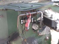
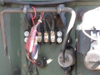
Hey 69, when my firewall plug wires deteriorated over time, I cut them off, crimped on some connectors and mounted them to a small black 4-position terminal block (the kind you can get at any Radio Shack) that was screwed to the firewall just above where the wires came through the metal.

I wasn't worried about corrosion since every connector was now stainless or aluminum and clearly visible to verify their condition. As you can see, there is some rust on the tops of the screws now, after about 15 years, but the connections were super good right up to the day I parked it.

I was just fixing a slight problem with the wires (broken connection just ahead of the plug), but in your case, depending on the condition of the engine-side wires, you could even make your own new wire runs, bypassing the old 3-prong connector completely, and since you wouldn't have to worry about mating them up to the old factory connector, it would be pretty simple.
And that way you'd KNOW the condition of all your wires.

Paul
 

Attachments

  • IMG_0697 (Medium).JPG
    IMG_0697 (Medium).JPG
    74.9 KB · Views: 21
  • IMG_0700 (Medium).JPG
    IMG_0700 (Medium).JPG
    68.4 KB · Views: 19
OP
OP
69bronco69

69bronco69

Full Member
Joined
Jul 9, 2011
Messages
190
Loc.
Central Arkansas
Test alternator at Orielly's - it passed. Reinstalled new VR and old alternator. 12.4 volts with key off. 11.2 volts on start. 14.01 volts with engine at idle. Thanks for the helps guys

ordered new vr plug

I may just put new wires from 3 prong quick connect plug at firewall to the coil and other two terminals. Then remove the green wire that was spliced from coil to an after market fuel gauge then to rear stud terminal on ign sw. That should solve hot coil with key in ACC position.

I'll let you know what I find out
 

DirtDonk

Contributor
Bronco Guru
Joined
Nov 3, 2003
Messages
49,353
And if you haven't already, even if you're still using the gauge, disconnect that wire now. You don't want a wire feeding a fuel gauge hooked to your coil at any point.

You can find a better place to get it's power from than your ignition fairly quickly I would think.

Paul.

Paul
 
OP
OP
69bronco69

69bronco69

Full Member
Joined
Jul 9, 2011
Messages
190
Loc.
Central Arkansas
And if you haven't already, even if you're still using the gauge, disconnect that wire now. You don't want a wire feeding a fuel gauge hooked to your coil at any point.

You can find a better place to get it's power from than your ignition fairly quickly I would think.

Paul.

Paul

All wiring done. Ran new wire from firewall plug to coil. Removed green wire from coil to stud of ign switch. Fires right up and keeps running when key goes from start to run. If I turn the key from run to ACC real quick, it dies like it is supposed to. Coil no longer gets hot with key in ACC position. Maybe I saved my coil and my points.

Thanks a bunch guys for helping a newbie - I'm learning;D

john
 
Top