• Welcome to ClassicBroncos! - You are currently viewing the forums as a GUEST. To take advantage of all the site features, please take a moment to register. It's fast, simple and absolutely free. So please join our community today!
    If you have problems registering or can't log into your account, please contact Admin.

1975 Stock Vacuum Question - Solenoid

JT

Full Member
Joined
Sep 14, 2012
Messages
159
Ok guys...I'm so very close to having this figured out but need a little help to get me across the goal line.

I've been researching vacuum line routing for my 1975. My intent is to take it back to stock (provided I can get the right air pump, diverter valve, etc.).

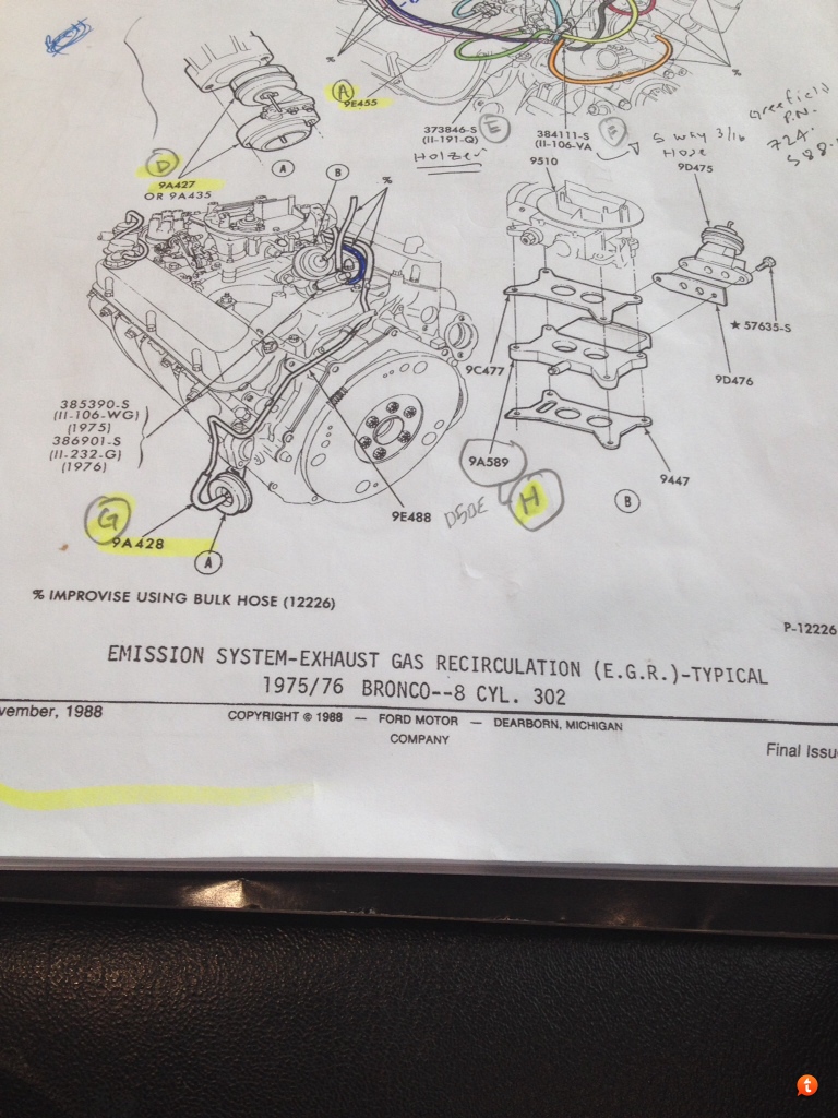
In my master parts catalog (illustration section) I have the diagram in pic 1. I've been piecing together the components but couldn't for the life of me figure out what the green highlighted part was (the part with the red and black vacuum lines going into it)...that is until I came across the diagram in pic 2. In pic 2, the part marked "12" is the vacuum solenoid.

I'm pretty sure that the red line in pic 1 is the same as the line in pic 2 going from item 12 to item 15. The black line in pic 1 appears to be the same as the line in pic 2 going from the vacuum tree in branching to the PVS item 13 and also to the vacuum solenoid item 12.

There are, however, two problems:

1) I searched my master parts catalog (part list section) I can't find the part # for the vacuum solenoid.
2) Even if I had the vacuum solenoid, it appears that it is a powered part and I have no idea how to get power to it or what connector to use.

By the way, Pic 3 is from my shop manual and confirms the general vacuum line routing for the EGR and distributor (albeit simpler than pic 1 and pic 2 do).

Any help you guys can give on the vacuum solenoid and how to power it would be a big help.

As always...thanks.

JT


Pic 1
9yguputy.jpg


Pic 2
emana6u5.jpg


Pic 3
e6etu5un.jpg
 
Last edited:
OP
OP
JT

JT

Full Member
Joined
Sep 14, 2012
Messages
159
Calling DirtDonk and Viperwolf...
 

DirtDonk

Contributor
Bronco Guru
Joined
Nov 3, 2003
Messages
49,452
I'm not always certain about different vacuum routings either. Especially with regard to '70's vehicles!
First though, are you sure that diagram is specifically for a Bronco? They varied IMMENSELY based on car or truck model, and not just by year. But it sounds like you've at least confirmed part of it with your shop manual. Manual is specifically for an EB?

I don't even know for certain that this one is for an EB, but I saved it years ago and it's marked "75FED" (for federal spec) so hopefully it's at least for trucks and utility type vehicles. Same as your diagram? Do you have the complete image of it to confirm?
75fed%20vacuum.jpg

Looks like the numbering remains the same, and #12 is the same thing as your green-meanie.

That's as far as I can go today. I just looked for under hood pics of our '76 at the shop but could not find any pertaining to that part. I'll keep looking, but if I don't find anything we might have to wait until Monday for me to go take some more beauty-shots under the hood and see what there is to see. Hopefully there are enough similarities between your '75 and the '76 to work with.

Good luck.
Looking on the gloomy side, it's very possible that your part is not listed because it hasn't been available for the last century or two. %). Being smog related, you'd think that every bit of that stuff would be commonly reproduced. Maybe they found out that not having it didn't cause enough trouble to be worth it? Don't know...

Paul
 
OP
OP
JT

JT

Full Member
Joined
Sep 14, 2012
Messages
159
Paul,

Thanks for the response. Pic 1 came from the Ford '74 thru '79 master parts catalog. It appears that broncos from both '75 and '76 had the same vacuum routing. Here is a pic of the bottom of the page:

u3yryven.jpg


I found Pic 2 on the internet.

The reason I say I can't find the part number for the solenoid is based on me searching the parts list in the master parts catalog. I do find some vacuum solenoids a but not for the 302.

If you don't mind looking at your '76 and letting me know I'd certainly appreciate it.

Thanks,

JT
 

DirtDonk

Contributor
Bronco Guru
Joined
Nov 3, 2003
Messages
49,452
Not a problem. Sure wish I could find all the images I've taken over the last couple of years! I bet there's at least one of that little bugger in there.

Paul
 

Rustytruck

Bronco Guru
Joined
Feb 24, 2002
Messages
10,875
here's one for a 1975 460. It looks like it shuts of the egr probably when you decelerate to stop the popping in the exhaust. what actually triggers it I dont know. 1974 didn't use it, it use a vacuum amplifyer. A large round plastic disc on the rear of the intake manifold on the passengers side with several vacuum lines running to it. 1975 they dumped the amplifyer.

http://www.ebay.com/itm/NEW-OEM-For...ies&hash=item35d3d824f1&vxp=mtr#ht_120wt_1161
 
OP
OP
JT

JT

Full Member
Joined
Sep 14, 2012
Messages
159
here's one for a 1975 460. It looks like it shuts of the egr probably when you decelerate to stop the popping in the exhaust. what actually triggers it I dont know. 1974 didn't use it, it use a vacuum amplifyer. A large round plastic disc on the rear of the intake manifold on the passengers side with several vacuum lines running to it. 1975 they dumped the amplifyer.


http://www.ebay.com/itm/NEW-OEM-For...ies&hash=item35d3d824f1&vxp=mtr#ht_120wt_1161


Rustytruck...Concidentally I just came to the same conclusion you did.


What I did was search the master parts catalog for "vacuum". I wrote down every "hit" that looked remotely close to something having to do with emissions, EGR, etc. I came up with 4 possibilities and then did searches for those parts inside the master parts catalog. The 9D474 was one hit that is used on 460cc engines, however, it listed a couple other alternate part numbers including 12A170. When I did a search for 12A170 I found this pic:


8a7u3uqa.jpg


Then I searched the web and found a similar part (see here) to the one you posted.


bune8aty.jpg


Now, I did a search for the part D2AZ-12A170-B per the parts catalog and found two of them. The strange thing is that the MPS also shows that this part is "not replaced".


So I seem to have answered one of my original questions: what part is it? Answer: D2AZ-12A170-B.


Now, there are a several questions remaining:


1) How do I get power to it?

2) What connector do I use?

3) Since the MPS says it's "not replaced", Do I even need it?

4) If not, how do I route the vacuum lines to the Air Pump Diverter Valve?


Paul, this is where I think your pics (fingers crossed) will help out.


Thanks Rusty and Paul


JT
 

DirtDonk

Contributor
Bronco Guru
Joined
Nov 3, 2003
Messages
49,452
Funny about that amplifier Rusty. My F350 with a 400 has one of those still. And it's a '79 with, I think, Federal specifications.

Anybody that's now having the joy of working with a mid to late-seventies rig and trying to fight their way around the smog devices can understand what we were dealing with when they were new and literally almost nobody outside of the original design engineers knew what they did!
We'd scratch our heads too, and good luck finding replacements anywhere. Because nobody else knew about them either, and the parts databases hardly covered that stuff unless you went straight to the dealers. And you know how short a time dealers like to keep their databases current. After about 10 years or so, they won't have the info either.
Coincidentally right about the time most things start to wear out or fail. Ugh...

Even though the modern stuff is more sophisticated, and more effective, it's also easier to understand the function thereof. Yeah, now we just say it's "controlled by the computer" and we're done with it. ;D The old stuff was just black magic twisted together by voodoo chants and burning incense.
Back then, it was hard to figure out just what timing and switching was coming from where and effecting what. Even though there were fewer wires and almost no sensors, other than water temp based thermal switches.

My '83 F150 had three of those little doo-dads on a bracket on the driver's valve cover. Never knew if they were working properly or not but they clicked every now and then and made funny buzzing noises once in awhile, so I left them alone.

The real corker for me was one day after fiddling with relays and delay valves and diverters and such, it turned out the darn thing did have a computer after all! A super early EEC system that I thought hadn't come out until the year after.
And one little finicky Ford-specific relay that controlled the power to it. Boy, what a revelation that was!
Finally got it running again by jiggering that relay with a standard Bosch style.

Sorry for the ranting on... I just saw those images you posted and went off to a dark place. :(

Paul
 
OP
OP
JT

JT

Full Member
Joined
Sep 14, 2012
Messages
159
Paul and Rusty,

I'm second guessing myself now...why would this part that supposedly goes to the air pump valve be called a "distributor modulator valve"?

What am I missing?

signed: confused in Michigan (aka JT)
 

DirtDonk

Contributor
Bronco Guru
Joined
Nov 3, 2003
Messages
49,452
I'd say it's either because it's still got something to do with ignition timing, is connected to something that has something to do with the distributor, or it's actually the same part as a similar function on some distributors. Or, by "distributor" they're merely talking about the vacuum distribution network. AKA the spaghetti factory. ;D

Paul
 

Rustytruck

Bronco Guru
Joined
Feb 24, 2002
Messages
10,875
(If) the Bronco had this vacuum valve it would show in the 1975 wiring diagram. I belive this valve has to do with closing the EGR as opposed to the AIR which has its own vacuum control with the vacuum diverter valve. Egr and air must shut off when decelerating and at idle or else at idle the engine will stall and when decelerating your fuel goes high and the extra gas it will explode in the exhaust stream causing backfiring. With out a computer to control fuel management you go along at 50 mph and let off the gas the butteryflies close cutting off oxygen and creating high vacuum in the carb pulling in extra fuel without the oxygen to support clean burning. In the 1975 and later your dealing with red hot cats and the high fuel and oxygen from the AIR pump could cause excessively high cat temperatures burning out the system.
 

Rustytruck

Bronco Guru
Joined
Feb 24, 2002
Messages
10,875
One thing to remember with Ford manuals. Ford started building the 1975 Bronco about August 1974 for the 1975 model year. The manuals and dealer network of parts manuals we usualy not available until mid 1975 and the next year they changed them for the next model year. The manuals you bought from Helm supplier for Ford at the time didnt sell to the public until the truck was about 2 years old and it usually came with a revision / suplement manual. All of these issues was caused by California state emission standards being stricter than Federal there was so much confusion going on with the manufactures no one could keep up and everything was backfilled as time permitted. Remember this was the time of gas wars and car sales were in the toilet and the largest market for cars in the whole world was California. No one had the guts to tell the cash cow California to stuff it. At least you don't have to deal with the NOX retrofit on top of all this crap like we did.
 
OP
OP
JT

JT

Full Member
Joined
Sep 14, 2012
Messages
159
I will check the wiring diagram in my shop manual...thanks for the idea Rusty.
 
OP
OP
JT

JT

Full Member
Joined
Sep 14, 2012
Messages
159
...I don't even know for certain that this one is for an EB, but I saved it years ago and it's marked "75FED" (for federal spec) so hopefully it's at least for trucks and utility type vehicles. Same as your diagram? Do you have the complete image of it to confirm?
View attachment 336093 ...

Paul,

I ended up finding a book online by Mitchell Manuals titled "1975-82 Vacuum Circuits Domestic Cars & Light Trucks". For the 1975 Bronco, there were two vacuum line routings depending on the Calibration Number for the engine. This calibration number was on a sticker on the left valve cover. There were three calibration numbers: 53L, 54L (mine) and 54M. This book lists 53L and 54M as Federal, however 53L and 54L have the same vacuum routing.

The 2nd pic that I originally posted (the same as the one you posted) is vacuum diagram Fig. 8 and corresponds to the 54M. I've attached a pic of my engine sticker (notice the 54L in the upper right of the sticker), the reference chart and the actual vacuum routing for my engine:

jebypety.jpg


ebevybu8.jpg


uvu3aqu4.jpg


The routings are very, very similar with the only real difference being the routing of the vacuum line from the bottom port of the PVS item #9.

I look forward to your pics on Monday.

Thanks,

JT
 
Last edited:

Fallingcedar

Jr. Member
Joined
Aug 6, 2015
Messages
54
Attempting to correct 1975 vacuum system

JT,
Thanks for posting these. I really appreciate all your research and for sharing. This provides a pretty valuable place for a newb to start.

I recently obtained a 1975 Ranger with a 3 speed manual in fairly original condition. It gave my uncle (the original owner) fits in the last two years and some shops in his town have worked on it. It has a new carburator and an electric fuel pump added. The catalytic converter was removed in the late 70's.

The 302 starts and runs okay. It stalls when it gets hot, about 1 mile or 2. It will restart momentarily and stall a few seconds later. Let it completely cool off and you are good for another trip around the block, neighbors think I'm nuts!

I have been looking to the vacuum system as a possible culprit. This diagram is how I found it. The loop on "13?" looked suspicous to me and there is a screw closing one port on the double T. Unlike your drawing, my "13?" valve has electrical connectors on top, one to ignition power, the other to the sensor on the air cleaner just like the solonoid "#12".

This weekend is shot, I'll be trying to reroute via your diagram and see if that works. I'll be sure to let you guys know how it turns out.

47763
 

Fallingcedar

Jr. Member
Joined
Aug 6, 2015
Messages
54
Update,
Starting completely fresh with new hose and following JT's Figure 7, I was able to solve my problem. Drove around all afternoon today, Thanks to all the guys who post on this forum. My only departure from the Figure 7 is the line from the intake manifold port to the 'bimetal sensor'. Can anyone help me ID the bimetal sensor?
 

Viperwolf1

Contributor
electron whisperer
Joined
Aug 23, 2007
Messages
24,347
Update,
Starting completely fresh with new hose and following JT's Figure 7, I was able to solve my problem. Drove around all afternoon today, Thanks to all the guys who post on this forum. My only departure from the Figure 7 is the line from the intake manifold port to the 'bimetal sensor'. Can anyone help me ID the bimetal sensor?

The bimetal sensor is in the air cleaner.
 
Top