• Welcome to ClassicBroncos! - You are currently viewing the forums as a GUEST. To take advantage of all the site features, please take a moment to register. It's fast, simple and absolutely free. So please join our community today!
    If you have problems registering or can't log into your account, please contact Admin.

Horn on Aftermarket Column

DeezNCSU

Jr. Member
Joined
Mar 12, 2014
Messages
224
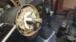
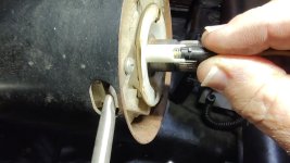
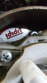
I have a new to me 69 Bronco and the horn isn't working so I'm trying to sort that out. I'm not sure what brand column or steering wheel it is, but it's an aftermarket tilt column and aftermarket woodgrain wheel. There is a 6002 printed on the steering wheel hub, if that helps. The horn doesn't work, so I pulled the wheel off, but I'm not exactly sure what is missing or why it's not working. The blue wire was connected inside the adapter and I assume red spring was in one of holes, however, I didn't notice which one (oops).

Here's a google photo link to a few pics, hopefully this works for sharing.

https://photos.app.goo.gl/iU9qGEcdwrxRCsZE9
 

904Bronco

Contributor
Bronco Guru
Joined
Sep 28, 2004
Messages
5,951
Loc.
San Martin, CA
At first glance it looks like an Ididit column, but there are cheap off-shore units that look somewhat similar.
It looks, by your pictures that the spring loaded contact (red wire) has come out of the turn signal switch assembly, which passes through the spacer hub. You will need to remove the spacer to get to that to see if it is damaged. (last one I fixed was) It looks like they were using the spacer hub to provide the ground to activate the horn. (Aftermarket wiring harness?) When you remove the spacer hub, if it is an Ididit column, there will be a tag that will identify it as an Ididit column and there will be a serial number. That will be helpful for them, if you need to order a new switch.
You will need to remove the large center nut and borrow/rent a steering wheel puller to get that spacer hub off.
(Pictures enclosed for reference)
Once you get the hub off, you should be able to ground the contact point where the spring loaded red wire goes and that will ensure the rest of your horn electrical system is working.
 

Attachments

  • IMG_20240303_141407319.jpg
    IMG_20240303_141407319.jpg
    91.6 KB · Views: 24
  • IMG_20240303_141429811.jpg
    IMG_20240303_141429811.jpg
    120.2 KB · Views: 22
  • IMG_20240303_142502724.jpg
    IMG_20240303_142502724.jpg
    86.5 KB · Views: 23
OP
OP
DeezNCSU

DeezNCSU

Jr. Member
Joined
Mar 12, 2014
Messages
224
I confirmed it is an IDIDIT column from Wild Horses.. In looking online, it says they work on 73-77 models and this is a 69, which I'm guessing is why the horn isn't working. I tested the horn itself and it does work going straight to the battery. I'm seeing in old posts that I need a relay to make it work, but I'm not certain on that or how to wire the relay if so.
 
Last edited:

904Bronco

Contributor
Bronco Guru
Joined
Sep 28, 2004
Messages
5,951
Loc.
San Martin, CA
I confirmed it is an IDIDIT column from Wild Horses.. In looking online, it says they work on 73-77 models and this is a 69, which I'm guessing is why the horn isn't working. I tested the horn itself and it does work going straight to the battery. I'm seeing in old posts that I need a relay to make it work, but I'm not certain on that or how to wire the relay if so.

If memory serves, 69 would have been a two contact horn ring since the factory wiring harness did not use a relay.

Ididit is set up to use a relay, although with any wiring, things can be modified. But that can be difficult to put into words what needs done and worse if wiring isn't your thing.
Your going to need a power source for the relay, the horn button is going to be the ground to activate the relay, and then a connection to the horn itself. The steering column has to be grounded so as in your picture, the hub adapter can supply it. Sometimes it is and sometimes you have to add it.

Dirtdonk (Paul) is usually good with all the wire colors , I am hoping he will chime in with which ones you need to look for. I would just pull out the continuity tester, with test light and figure that out on the fly. I am sorry I cannot give you the direct simple answer that you are looking for...

Have you looked at the wiring to the column yet? Did they retain the Ford square connectors (Factory) or did they install a GM type long skinny connector that the Ididit column typically has.
 

904Bronco

Contributor
Bronco Guru
Joined
Sep 28, 2004
Messages
5,951
Loc.
San Martin, CA
The horn wires on your harness should be a yellow and blue/yellow strip. Both should be a larger gauge. Since I just found out that the 73 that I am working on needs the turn signal switch replaced - doesn't cancel on turns, I might have more info to add later.
 

DirtDonk

Contributor
Bronco Guru
Joined
Nov 3, 2003
Messages
48,964
Don’t forget Doug, if the turn signal switches working perfectly fine, electrically, and if it’s just a broken canceling cam, you can buy the cam arms separately.
 

904Bronco

Contributor
Bronco Guru
Joined
Sep 28, 2004
Messages
5,951
Loc.
San Martin, CA
Don’t forget Doug, if the turn signal switches working perfectly fine, electrically, and if it’s just a broken canceling cam, you can buy the cam arms separately.

The new AAW harness box had a new turn signal switch assembly in it, but the Owner and the previous assembly guy didn't remember why it was there. Now we know why ;).

One of those stories where parts were bought so long ago that no one can remember... AAW Bronco wiring harness is 2016 vintage/first gen, Edelbrock carb has a production date of 2013, GM one wire Alt was bought in 2018...
 
OP
OP
DeezNCSU

DeezNCSU

Jr. Member
Joined
Mar 12, 2014
Messages
224
I found a post that Paul made previously about adding a new Bosch style relay and tried that, still no dice. It looks like the wires from the column were butt spliced into other wires and taped up so I guess I'm going to have to cut that open next. I tried a test light on the copper prongs under the steering wheel adapter and none have any power to them. All the other electrical components appear to be working as they should.

I assume the black wire from the column should be connected to the blue/yellow wire under the dash?
 
Last edited:

DirtDonk

Contributor
Bronco Guru
Joined
Nov 3, 2003
Messages
48,964
Which way did you hook up the relay?
Did you connect it like I suggested connecting a stock column in a pre-74? Or like a later model?
The two wiring schemes would be completely different.
Since you’re working with a later column, you would connect it like a 74 or later.
 
OP
OP
DeezNCSU

DeezNCSU

Jr. Member
Joined
Mar 12, 2014
Messages
224
Which way did you hook up the relay?
Did you connect it like I suggested connecting a stock column in a pre-74? Or like a later model?
The two wiring schemes would be completely different.
Since you’re working with a later column, you would connect it like a 74 or later.
Which way did you hook up the relay?
Did you connect it like I suggested connecting a stock column in a pre-74? Or like a later model?
The two wiring schemes would be completely different.
Since you’re working with a later column, you would connect it like a 74 or later.
Thanks for the response. I wired it like this:
Pin 30 = positive/battery - ran a wire straight from the positive battery post
Pin 85 = ground wire from body
Pin 86 = original blue/yellow horn wire
Pin 87 = wire to horn terminal
 

DirtDonk

Contributor
Bronco Guru
Joined
Nov 3, 2003
Messages
48,964
Don’t think that will work. You essentially have two grounds then.
You need power from the battery to pin 30 just like you said.
You also need power to pin 86 and you can simply jumper 30 to 86.
Then pin 85 (oops. Thanks Oldtimer) goes to the steering column wire, which in turn grounds the relay circuit, switching it on when you hit the horn button.
Pin 87 goes directly to the horn. The horn grounds through its body where it’s bolted to the vehicle body.
 
Last edited:
OP
OP
DeezNCSU

DeezNCSU

Jr. Member
Joined
Mar 12, 2014
Messages
224
Don’t think that will work. You essentially have two grounds then.
You need power from the battery to pin 30 just like you said.
You also need power to pin 86 and you can simply jumper 30 to 86.
Then pin 87 goes to the steering column wire, which in turn grounds the relay circuit, switching it on when you hit the horn button.
Pin 87 goes directly to the horn. The horn grounds through its body where it’s bolted to the vehicle body.
OK, I tried this combo and still nothing.

30 - jumped to 86
86 - wire to 12V+
85 - blue/yellow wire from harness
87 - to horn
 
Last edited:

Oldtimer

Contributor
Jr. Member with Sr. moments
Joined
Feb 4, 2005
Messages
1,165
Loc.
Sunnyvale, CA
What you did should work . . if the blue/yellow wire goes to ground when you push horn button.
Try grounding pin 85 at relay to test power to relay to horn circuit.


1736824845270.png


Need to figure out what PO did to wire routing.
Stock 69 harness takes
12v from headlight switch,
sends it to horn button on yellow wire,
then to horn on blue/yellow wire,
thru horn to chassi ground.

1736825450625.png


Paul, typo in post #12, pin 85 (not 87) goes to column wire.
 
OP
OP
DeezNCSU

DeezNCSU

Jr. Member
Joined
Mar 12, 2014
Messages
224
Thanks for all the feedback. I figured I would need to cut into the harness under the dash, so that'll be my next move. I'll report back on what I find.

To confirm, the black wire from the ididit column should be attached to a yellow wire coming from the headlight switch?
 

Oldtimer

Contributor
Jr. Member with Sr. moments
Joined
Feb 4, 2005
Messages
1,165
Loc.
Sunnyvale, CA
I know nothing about Idit column schematics, but the steering wheel adapter posted at start of this thread is connecting a wire in column to ground. If it is the black wire, you DO NOT want to connect it to the yellow wire from headlight switch.
 

DirtDonk

Contributor
Bronco Guru
Joined
Nov 3, 2003
Messages
48,964
Also, on the relay, is there a diode in it?
If it’s a new relay, you should be able to tell by the diagram printed on the side.
Reason I ask is that, while almost all early diagrams, especially from Hella, show 85 as ground and 86 as power, some do the opposite.
And if there’s a diode, your brand may want 85 as power and 86 as ground.
I don’t know for a fact that this is how they work, because the diode might be in the 87 circuit. But you can tell this from your printed diagram.

Most cube relays are functional in either orientation.
 

DirtDonk

Contributor
Bronco Guru
Joined
Nov 3, 2003
Messages
48,964
As another test, in addition to testing the relay and horn by grounding your current 85 terminal wire, you can verify with your ohm meter that your column wire (whether it be black or other color) is in fact, grounding when you push the horn button.
You may have it wired perfectly correct right now, and the horn button is simply not working.
 
OP
OP
DeezNCSU

DeezNCSU

Jr. Member
Joined
Mar 12, 2014
Messages
224
There is no diode in the relay I have been using. I grounded pin 85 as suggested and the horn works, so I'm back to thinking the blue/yellow wire is the issue. I'll dig into the wiring coming from the column next.
 
Last edited:

DirtDonk

Contributor
Bronco Guru
Joined
Nov 3, 2003
Messages
48,964
Whatever the correct wire in the column is (maybe it's the Black one?), you should be able to test it just by touching one probe of your meter to the wire, then the other to ground.
Just the way it is, you should get no reading (infinite resistance) buts when you press the horn button up top, that should change immediately to zero ohms (fully connected).

If it does not change when you press the horn button, then the fault is in the column, or "with" the column.
Meaning that it's either the wire is bad, or the column is not sufficiently grounded.
What kind of shaft do you have from the column to the gearbox? If it's using a rag-joint coupler, then you may need to create a ground jumper between the upper and lower shafts.
If it's already coupled with metal, you may have to figure out a way to properly ground the horn button so that when it's pressed it will connect to ground.

In other words, "all you have to do" (haha!) is get that #85 pin to ground when you hit the horn button.
See? Simple, right? Not always! ;)

Paul
 
Top