• Welcome to ClassicBroncos! - You are currently viewing the forums as a GUEST. To take advantage of all the site features, please take a moment to register. It's fast, simple and absolutely free. So please join our community today!
    If you have problems registering or can't log into your account, please contact Admin.

363W Build - Excessive Cam Lift at Valve?

marjama

Contributor
Sr. Member
Joined
Nov 24, 2004
Messages
435
Hey all, I have been roadblocked by an issue on a new engine build for quite a while and thought I'd ask the collective about it.

I'm building a 363W for the Bronco, and ran into an interesting issue. I'm seeing substantially more lift at the valve than I expect, and I'm not sure how to proceed. Here's a bit more detail...

I ordered a custom roller cam from Woody at Fordstrokers, installed it, and checked it for lobe lift and timing. All was mostly spot on! All measurements were done in two different cam lobe pairs with hydraulic roller lifters that are set up to be solid. Initial valve measurements are with Comp Ultra Pro Magnum roller rockers in a 1.6 ratio. Here's the spec and the measurements:

Intake lobe lift spec: .355" - measures .354"
Exhaust lobe lift spec: .358" - measures .355"

Intake gross lift: .568" - measures .609"
Exhaust gross lift: .573" - measures .616"

That's the equivalent of a ~1.72:1 rocker ratio! On Woody's suggestion I bought a Scorpion / Trick Flow 1.6 rocker to test with assuming that Comp mis-marked the rockers, but ran into the same issue (.600 intake / .608 exhaust). Pulled an old Magnum rocker from my previous engine, and got generally the same result.

I'm baffled - it's a simple-ish geometry issue. I've tried longer and shorter push rod combinations - as an example, I was able to get the exhaust with the TF rocker down to .593, but the valve tip pattern is starting to get wide and shift off of center.

Any ideas? Has anyone run into this before? I've literally never measured any previous setups at the valve, so this is a new one to me. Now that I finally double checked my measurements along with the TF rocker test, I'll also get back to Woody. I'm sure I can run it and it'll be fine, but it's clearly not to spec. I'm baffled.
 
OP
OP
M

marjama

Contributor
Sr. Member
Joined
Nov 24, 2004
Messages
435
I have a message out to Woody, but the cam itself measures right on. So, I think it has to be associated with the valve train itself (or, something I am simply doing incorrectly).

Thanks!
 

EFI Guy

Sponsor/Vendor
TheEFIguy@gmail
Joined
Apr 14, 2013
Messages
1,119
Loc.
BFE
Dumb question, but are you measuring at a point that is dead center with the valve? I could see measuring further out causing higher readings.
 
OP
OP
M

marjama

Contributor
Sr. Member
Joined
Nov 24, 2004
Messages
435
How much did you shave the deck or head?
I didn't - stock FMS Boss 363 short block with new AFR heads on it.

Dumb question, but are you measuring at a point that is dead center with the valve? I could see measuring further out causing higher readings.
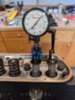
No questions are dumb - it's possible (likely?) that I'm doing something silly and not thinking about it! I'm measuring on the valve retainer, but I believe it should be travelling vertically with the valve. Here's an image of the setup:
 

Attachments

  • PXL_20250330_002454976.jpg
    PXL_20250330_002454976.jpg
    134.9 KB · Views: 36

73azbronco

Contributor
Bronco Guru
Joined
Nov 11, 2007
Messages
8,213
I know you can build to get .6 of lift, whats the max that engine/head/piston can take? Whats the tolerance allowable? And put some more clutter on that table it's to clean.
 

73azbronco

Contributor
Bronco Guru
Joined
Nov 11, 2007
Messages
8,213
I have a message out to Woody, but the cam itself measures right on. So, I think it has to be associated with the valve train itself (or, something I am simply doing incorrectly).

Thanks!
like base and lobe circle, he gave that number to you? And while it may measure to what he says it should measure, it might be a wrong design. I mean at your stage you know what you are doing, and the hardest part should be ensuring roller position on valve stem.
 
OP
OP
M

marjama

Contributor
Sr. Member
Joined
Nov 24, 2004
Messages
435
I know you can build to get .6 of lift, whats the max that engine/head/piston can take? Whats the tolerance allowable? And put some more clutter on that table it's to clean.
The valve springs are .650" max lift, so I'm technically fine there...but there isn't really a lot to gain with AFR heads above .580 from a flow perspective. I really don't know what the allowable tolerance is, but an extra .040" seems unreasonable, right?

like base and lobe circle, he gave that number to you? And while it may measure to what he says it should measure, it might be a wrong design. I mean at your stage you know what you are doing, and the hardest part should be ensuring roller position on valve stem.
Yeah, the number is on the Comp cam card that came with the cam from Jim. It's also (theoretically) just basic math: .358*1.6=.568 on the intake...so it's gotta be in the rocker.

Interesting too, that 1.72 is also a common rocker arm ratio.
100% - that was my initial belief too. Then I tried three other 1.6 rockers and generally got the same results. That's where I got stumped! This shouldn't be that complicated :)

Interested to see what Jim says about it...
Me too! I sent him a pretty detailed message - I'll keep you all posted on what I hear back.
 

frdboy

Contributor
Full Member
Joined
Jul 16, 2013
Messages
238
Have you checked with the real springs or just the light ones? Most rockers have extra ratio built into account for flex/deflection under actual load.
 
OP
OP
M

marjama

Contributor
Sr. Member
Joined
Nov 24, 2004
Messages
435
Have you checked with the real springs or just the light ones? Most rockers have extra ratio built into account for flex/deflection under actual load.
That's a good question - no, I haven't. I read something similar this morning about rockers having a bit of extra ratio in anticipation of deflection over on speed-talk.com, but it wasn't quite as extreme. It sure won't hurt to check though. I'll try it and report back.

Edit to add a link - this could be the answer: https://www.speed-talk.com/forum/viewtopic.php?t=3971
 

frdboy

Contributor
Full Member
Joined
Jul 16, 2013
Messages
238

EFI Guy

Sponsor/Vendor
TheEFIguy@gmail
Joined
Apr 14, 2013
Messages
1,119
Loc.
BFE
Wow. I never thought you would see that much deflection!
Years ago I remember seeing a video of an engine running filmed with a crazy high speed camera. The deflection in the crankshaft made it look like a wet noodle.
 
OP
OP
M

marjama

Contributor
Sr. Member
Joined
Nov 24, 2004
Messages
435
Updated lift at the valve with the actual springs and the intended Comp Pro Magnum rockers:

Intake spec: .568", measured .582"
Exhaust spec: .573", measured .591"

So, not perfect...but .014 and .018 over. Certainly better than .041"/.043"! No reply from Jim yet, but I think this is close enough to finally reassemble the motor and keep moving. I will circle back if Jim responds as well.

Thanks for all the comments!
 

pcf_mark

Bronco Guru
Joined
Jun 11, 2010
Messages
3,645
It sounds like they built in some lift to factor out the flex of the stud and rocker to get max valve action per the cam card. Neat..but also confusing. I bet they got questions why the next valve lift was not matching the card on assembled engine and got tired of it.
 
OP
OP
M

marjama

Contributor
Sr. Member
Joined
Nov 24, 2004
Messages
435
That's exactly what most of the engine builders I ran across were saying - given the great difference in spring pressure between checker springs and actual, I'm sure it no only pushes everything "together" a bit more and takes up all the slack, but it also compensates for various components flexing. I think what I read was "almost no one ever complained about having a little extra lift, but everyone complained about having too little!".
 
Top