...it appears that this yellow from the old voltage regulator should be connected to the "A" post on the 3g alternator/regulator.
No, it should be cut off & capped.
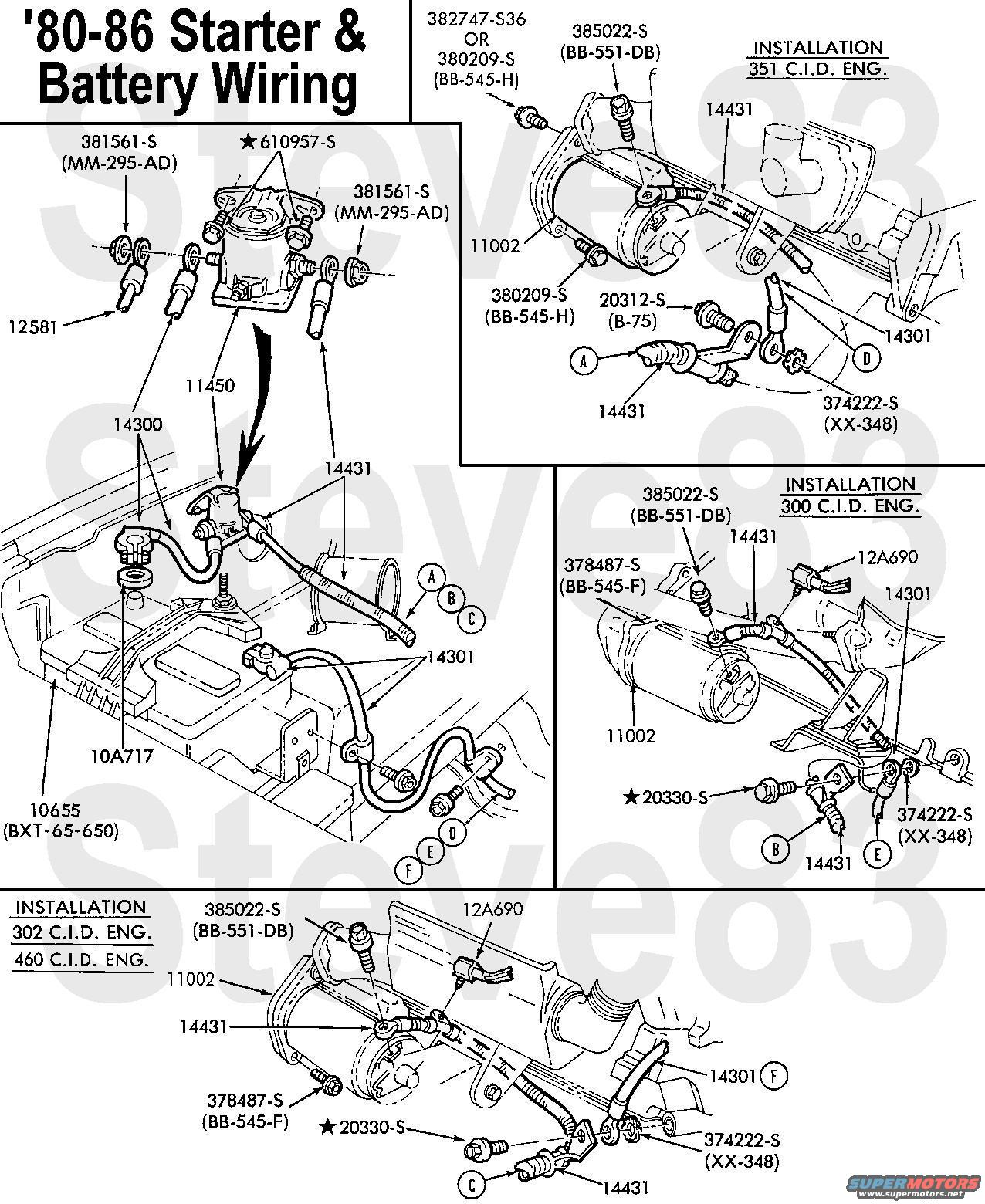
Black wire with the fusible link (38A) stays connected to the starter relay.
Yes.
...Green/red wire...should be connected to the "I" post on the 3g alternator/regulator.
Not directly - it should be spliced onto the LG/R wire on the 3G harness.
On the 3g alternator/regulator plug, it has the white/black wire (4) that just loops over to the actual alternator.
If you have a 6V carburetor choke heater, it can be spliced into that wire. Otherwise, it just stays like it is.
...an orange wire (35) that gets removed.
Yes, that circuit is internal to the 3G.
The black/yellow wire (37) that goes to the 1g alternator "B+" post gets capped off. No longer used.
It CAN be used, but not for any load that could pull more than ~30A, and certainly not for the 3G output.
The Black/red (26) between the old voltage regulator and the alternator gets capped off.
It could get discarded like Or 35; that circuit is obviated by the 3G VR being screwed to the 3G case.
A new 4awg cable is connected to the "B+" post on the 3g alternator and goes to an inline 175 amp fuse, then on to the Positive side of the starter relay (C211).
But if you're using the 3G harness, that's already included & built - you only connect the ring terminal from the short side of the fuse to the starter relay B+ post.
New 4awg cable from the Positive side of the starter relay to the Positive battery post (C211 to C207).
If your existing red B+ cable is in good condition, it can stay where it is - a new one isn't necessitated by the 3G.
...Negative side of the starter relay...
No such thing, so no such wire. One large post on the starter relay is always B+; the other post is momentarily connected to that (so also B+) during cranking.
New 4awg cable from Negative battery post to a ground post on the engine block...
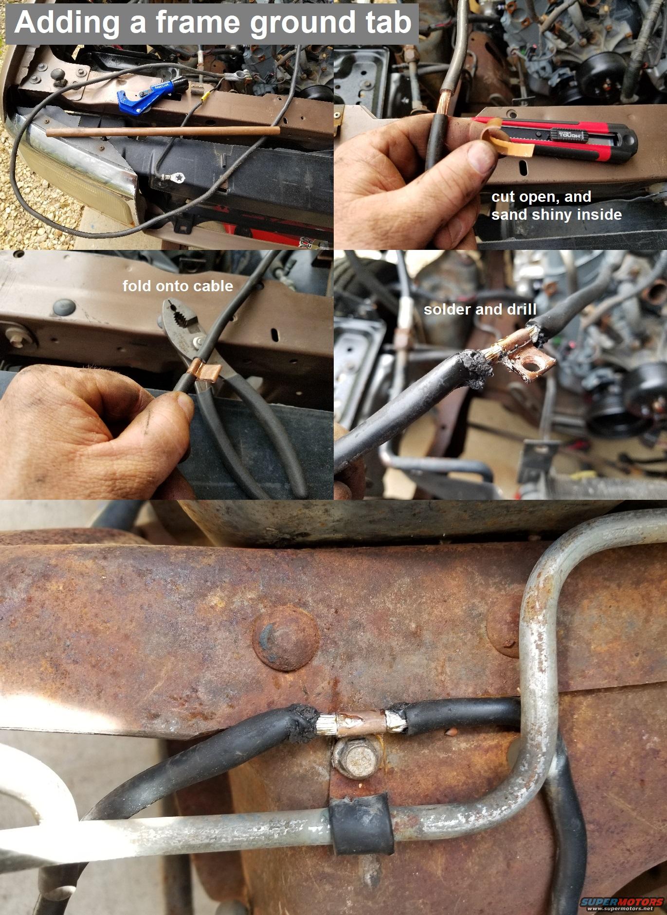
Again, only if there's a problem with the existing black B- cable. And for the best electrical grounding, that cable should also be grounded to the frame (by soldering a tab to it, and then screwing the tab to the frame), and a smaller (~8~12ga) ground wire should go from the B- clamp to the inner fender or core support to a spot without paint so it makes a good ground to the body sheet metal (like the old Bk/R 26).
Brown wire (262) stays connected to the "I" post on the starter relay (C214).
The ignition system is not impacted by the 3G, so yes that wire stays where it is.
Red/blue (32) wire stays connected to the "S" post on the starter relay (C213).
Right - cranking is also not affected by the 3G.