• Welcome to ClassicBroncos! - You are currently viewing the forums as a GUEST. To take advantage of all the site features, please take a moment to register. It's fast, simple and absolutely free. So please join our community today!
    If you have problems registering or can't log into your account, please contact Admin.

Electrical Gurus: Help! I'm still trying to grasp wiring headlights relays

Banjer Picker

Bronco Guru
Joined
Sep 25, 2006
Messages
1,357
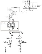
1st question(s): Do the headlight and dimmer switches operate under 12 volts on a factory wiring harness? Are there any fuses between positive batter terminal and the light switch?

Next area:

*I've read numerous articles on upgrading headlights with two 12v 30 amp relays, but each one I read, tells you a completely different configuration (schematic) to wire the 4 posts (30, 87, 85 & 86). I know what the inside of the relays look like and the mechanics behind what makes them work, so I don't understand how you can wire them 6 different ways and still get the same end effect? Which is THE RIGHT way?

*With the the relay upgrades: If I have to run a 20 amp fuse between the positive battery terminal and relay, why dont I have to run a fuse between the positve battery terminal and the light switch?

*Getting frustrated. :-X Any insight is VERY appreciated.
 

Viperwolf1

Contributor
electron whisperer
Joined
Aug 23, 2007
Messages
24,335
1st answer: Yes. There's a fusible link near the starter solenoid and the thermal breaker in the headlight switch. That's why you don't need a fuse there.

There are several ways you can wire the relays. It all depends on what you use for the goesintos and the comesoutofs.

Here is a Bronco specific diagram.
 

Attachments

  • headlight relays.jpg
    headlight relays.jpg
    50.1 KB · Views: 61

DirtDonk

Contributor
Bronco Guru
Joined
Nov 3, 2003
Messages
47,872
Yes, 12 volts. On a Bronco (as on most older vehicles) they're just a standard two-way switch in-line between the light switch and the lights.

One thing that might help along the way is to always look at a relay as simply a "remote switch" in your system. Picture your existing dash switches as low quality (they're not really), low power capable switches. With a relay, they're now being used to switch on a higher power capable switch.
And, in most cases, and the best reason for using them, is the relay can be mounted in such a way as it's closer to the battery and the accessory (in this case, the headlights) so that there is a shorter run of wire between the battery's 12 volts and the lights needs.
Shorter wire means less loss of voltage over it's length. Or, as in the case of an older vehicle being retrofitted, newer wire with clean connections as well.
Hence the usually brighter lights.

This also means that the builder (you or the O.E.) can use a cheaper, smaller, lighter-duty switch, smaller gauge wires, thereby saving money and weight (lots of wires in a modern car) and run a more powerful accessory without hurting anything and risking a meltdown.

That's a lot of blah blah blah, to try to describe something you may already know, but it helped me when I just started thinking of relays as remote switches. Which is what they are of course. Helping to better relay power between the battery, control switch and the component. Which is why they're called "relays" anyway.

Paul
 

DirtDonk

Contributor
Bronco Guru
Joined
Nov 3, 2003
Messages
47,872
*I've read numerous articles on upgrading headlights with two 12v 30 amp relays, but each one I read, tells you a completely different configuration (schematic) to wire the 4 posts (30, 87, 85 & 86).

You really shouldn't be seeing that anywhere Banjer Picker. Those four numbers (five, if you include the 87a on some relays) are an International Standard wiring diagram and stay the same no matter what.
The only time I've ever seen a difference is when one person says that the 85 is ground and 86 the switch, and the other says vice-versa.
With some relays, it doesn't actually matter, as the relay will work either way. But some systems are very specific and have to have 85 and 86 wired a specific way. I always forget which one is which, so a book, or Viper, can tell you specifically.

Fuse protected or not, #30 is ALWAYS direct from the battery to the relay.
Fuse protected or not, #87 is ALWAYS out to the accessory.
Numbers 85 and 86 are ALWAYS the ground and switched 12 volts (from the dash switch or other circuit controller).


*With the the relay upgrades: If I have to run a 20 amp fuse between the positive battery terminal and relay, why dont I have to run a fuse between the positve battery terminal and the light switch?

Viper already answered the part about the existing protection in the switch circuit, so I'll just add that you're asked to put a fuse inline from the battery because that's an all new circuit, between the battery and lights, therefore has no existing protection from the factory.
And 20 amps is just a generic number because they don't really know what lamps you're going to be using. If you figure out the actual amp draw, your low-beams are barely pulling 10 amps, and your high-beams are pulling anywhere from 10 to 25 amps (depending on what bulbs you're using). So the 20 amp fuses are are simply a good round number that should work for most installations.
And the reason they specify 30 amp relays is mostly because that's the most common standard type. Lesser rated relays are not as common and it doesn't hurt to over-kill your needs anyway. Probably promotes a long life for the relay.

Paul
 
OP
OP
Banjer Picker

Banjer Picker

Bronco Guru
Joined
Sep 25, 2006
Messages
1,357
Thank you! I feel much better about it now. Apparently I was on the right track initially but definitely got thrown off track by some of the hot-rodders schematics (home made) out on the internet.

Couple more questions if you don't mind.

I'll be replacing the factory on/off light switch with an aftermarket switch and circumventing the original wiring, fusable link, etc. Thanks to you guys, I now understand that I'll have to put a fuse between the power source and new light switch. What size fuse should go with? Is it dangerous (more prone to fire) to put a bigger fuse in?


Regarding the wiring from the power source to the #30 post on the relays: Is it best to draw power from the battery, the alternator or the selenoid?

Thanks again!
 

Viperwolf1

Contributor
electron whisperer
Joined
Aug 23, 2007
Messages
24,335
Since you're replacing the headlight switch you will want to fuse the the wire providing current to it. You'll need somewhere in the neighborhood of a 20 amp fuse if still using all the original lighting along with the headlight relays. The turn/hazard bulbs can draw over 8 amps, side marker bulbs draw over 1 amp, dash bulbs draw about 2 amps, and relays will draw a couple amps. A bigger fuse allows more current to flow through a short. The proper size fuse kills the current if a short occurs.

I'd pull relay power from the starter solenoid because it's easier to connect than to the battery. I wouldn't connect it to the alternator because it relies on a too complicated wiring path for a safety device like headlights.
 

Steve83

Bronco Guru
Joined
Jul 16, 2003
Messages
9,022
Loc.
Memphis, TN, USA, Earth, Milky Way
If you spend a few hours browsing your local junkyards (and there are some good ones in DFW), you can pick up a small fuse/relay box for a few bucks. Mount it near the battery, and run its main power input either directly to the battery clamp (by soldering - NOT by a ring under the nut), or to a ring on the starter relay (take the time to clean ALL the rings). Then you'll have plenty of fuses available for any future mods, and they'll be safe. The number of fuses & relays, and their styles, is up to you, but I'd get something that holds common ATC blade fuses and MAXI fuses (since that will give you the widest range of current ratings) and Bosch/ISO relays (since they're the most common, and can handle 30-40 Amps). Some Jeeps have a block that can be reconfigured by sliding sections in & out.

To choose a fuse for a particular circuit, consider ALL the loads (motors, lights, heaters, modules, solenoids, relays...) that will be on it, and find out how much current each one draws at 12V. Add them all up, add ~20% for surges, and use the next LARGER fuse. So if you have a pair of 55W fog lights (W=VxA, so 110W/12V=9.2A) and their relay (less than 0.5A), a 10A fuse would be borderline because there's no margin for surges. A 15A fuse would be appropriate.

Then you have to build the circuit using wiring that's capable of handling at least 20A. If the wiring is too small, it'll burn before the fuse, which defeats the purpose of the fuse.

The reason you found so many variations in circuits is that there are so many variations in style (some safe; some not-so-safe) and each has its own peculiarities and advantages.
 
Top