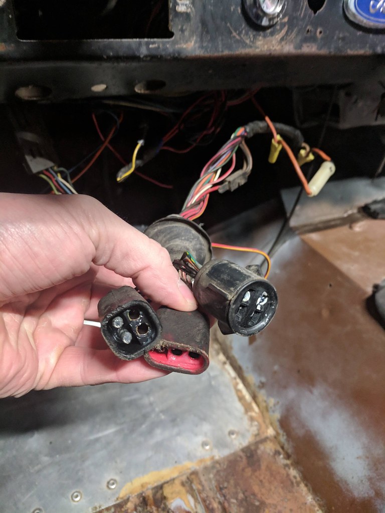
Here is a picture of the voltage regulator (thin blue wire is Sniper to fuel pump wire):
As suspected, that's not an original Bronco regulator connector/harness.
I've seen the ones like yours, with two Orange wires for some reason, but not in a long time. As long as the wires are connected as they should be though, your alternator should charge just fine.
If you're feeling bolt and adventurous though (and don't mind working with the visible grease) you could always re-orient the wires as they should be. Unfortunately that would mean re-doing some of your obviously new connections. So I would likely just leave it and get rid of the Green w/red wire for now. Using a special tool or pick you should be able to unclip the contact from the plastic housing and remove the wire entirely.
If you decide to go for it, you leave the first Orange wire and the third Yellow wires alone, and replace the second one with the Green w/red. Ending up with a blank spot in the fourth position.
Is there a way to test if it is powering up my voltmeter properly without the engine (alternator) running?
Not sure I understand. What volt-meter? Do you have a volt-meter in the original dash location? Or are you talking about an ammeter? If so, no there is no way to test your alternator's output without it spinning.
If you're talking about an actual voltmeter though, the alternator is not usually the source of the voltmeter wiring anyway. Not directly anyway.
Connect any voltmeters to wiring under the dash that is switched so it's not on all the time.
Funny you mention ammeter equipped... I have an ammeter, but it appears aftermarket... Is it?
Yes. Anything not inside the large round gauge cluster to the left of the steering wheel is always aftermarket.
Anything mounted under the dash is aftermarket.
Any ammeter that is a "direct-read" style (with two studs where the wires mount) is aftermarket. The factory ammeter has the same 60a range, but is an "inductive-read" style, with a metal loop on the back where the wire passes through.
It's passive, rather than hard-wired. Much safer!
(it did not work when running, but did have two very large wire running to it. One from the battery and one to the voltage regulator it appears, I assumed that he added it after the fact and interrupted the alternator to voltage regulator connection to detect amperage from alternator...)
Sounds like it. Get rid of it in my opinion. Were the two wires Black w/yellow?
Generally that type of ammeter does interrupt the flow, but not from the regulator. It's between the battery and the alternator. No connection to the regulator.
But one that uses a "shunt" to sample it's readings might use the voltage regulator. I don't know, but usually the shunted ones are the higher reading gauges. For example an 80a, 90a, or 100a or higher reading gauge.
Would this (red/green from ignition switch) be a good place to connect the switched 12v to my Sniper EFI? I have not located a good 12v switched source yet.
Maybe. Maybe not...
It sounds like you need it to power quite a few things. If that's the case, it's not up to it alone and should be used to trigger a relay instead, that has the capacity to power up all the accessories you're wanting it to control. Ignition, EFI, fuel pump, etc.
Its an added ground to ground the starter solenoid.
Cool. Good place to add an additional ground.
You should have a good supply of 10ga and 12ga and maybe even 14ga Black wire for your grounds. You will end up using a lot of it and it's then obviously a ground.
I know you've already done much of it, so maybe not this project. And besides, YOU know where the wires are... But it would help anyone that ever needs to work on your rig if they were Black.
Figure you knew that, but wanted to mention it anyway.
It goes to a larger blackish wire that goes to the voltage regulator.
That would be your sensing wire and that's how the regulator knows how much the alternator should put out. Keep it in good shape.
FYI though, most of these wires do not need to be large gauge heavy wires. Very little current is being carried through them. But no reason at this point to change anything. Just for future reference.
Yeah I added a few ground from the battery to engine ground, but I plan to add a few more and test around. I defiantly know the importance of good grounds.
I hate to change things in mid-stride here, but that is not the optimal place for your grounds. It's not bad to have a central source, and run others to it as a semi-direct path to the battery. But mounting it to the old alternator/air pump bracket is not the best location.
First, the farther away from the actual engine block, the more susceptible it is to reduced efficiency through connections that may get painted some day, and threads and bolts that may rust (if they are not already) and create resistance.
Your main battery ground cable should be directly to the engine block if that is available (which it usually is on our engines) and the closer you put it to the starter motor the better as well. Since the starter is the main drain on almost any vehicle, the closer you get the ground the better.
When you're adding grounds, add as many to the body as you can to keep all the electrical systems happy. Between the engine and firewall is a good spot.
If moving the current position of the main cable means you'll have to re-do all those others, well, you can keep it there for now. But if it was me I'd move it.
A side benefit, unless you're going to restore the smog pump, would be to remove that bracket completely and replace it with the basic alternator brackets that all non-pump equipped Broncos used. Simpler, easier to adjust and higher up for better access.
One of those small grounds should run between the alternator case and the voltage regulator by the way. You may already have one, but in case you don't that's another one to add.
I am installing the Hyperspark CDI, Coil, and Distributor cap also to wire into the Sniper EFI. That is why I am able to clean up a lot of the random wires in the engine bay. The previous owner had a lot of non-important splices into important things such as the coil power supply, which is now eliminated (Hyperspark Coil is powered from CDI directly which is connected directly to battery and Sniper EFI).
Where are you sourcing your switched power for the ignition? Or does that rely on the EFI computer too?
Do you still have easy access to the Red w/green wire? Remember that this is a resistor wire too, so is not designed to flow 12v at higher current levels. So if you use it as a source of power in ON and START, you will need it to power a relay.
I am spending a lot of time cleaning up the electronics that the previous owner has added or altered, but its hard to understand what can and cant be eliminated when adding a completely new ignition system that is self contained.
Since your wiring is still basically stock (minus all the PO mods) then anything that is in the original wiring diagrams regarding the alternator/charging system is to be left intact.
Pretty much everything in the book must remain, except in as much as you need to modify it now to fit your EFI needs.
The only connection to the Sniper/Hyperspark from the original wiring is 12v constant, ground, and 12v switched, the rest is self contained in the Sniper/Hyperspark system. However I fear that removing some of the old ignition wiring may result in unknown electronic gremlins down the road.
Yes it might. Especially given the hack job that's been done to it previously. But as you clean things up you should be able to see what's stock and what's been added.
One critical thing you need to know, wherever you follow that large Black w/yellow wire, check it out and make sure it's in one piece. It's the main power flow throughout the entire vehicle. Period.
If it's cut or disconnected, nothing works.
The only exception is if you re-wire the charging system to accommodate a more powerful alternator.
Still lots to do it looks like. And still lots to learn on your part as you go.
An EFI setup is not really plug-n-play when you have to build the supply chain from scratch like you're doing. Sure, the new wiring that comes with the computer is simple, but you still need to make sure your original setup is working at 100% effectiveness.
I'm sure you've seen it here time and time again, but probably 80% of EFI installation issues are due to faulty, or just old and tired factory wiring. Add enough hacks to the system, and it's just that much harder to track down the gremlins.
You're off to a good start. Just still lots more to do.
Paul