• Welcome to ClassicBroncos! - You are currently viewing the forums as a GUEST. To take advantage of all the site features, please take a moment to register. It's fast, simple and absolutely free. So please join our community today!
    If you have problems registering or can't log into your account, please contact Admin.

Power window wiring question.

awest5321

Contributor
Jr. Member
Joined
Feb 13, 2010
Messages
249
Loc.
Exit 79 on I85
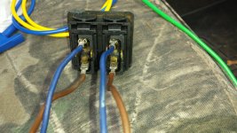
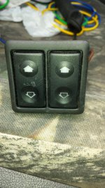
I am installing Wild Horses E Z Power Windows kit and need wiring instructions for the 6 pin window switches. Only using the double switch panel and putting it in the front of my center console to control both windows. No switches on my doors. I do not have instructions for wiring because I bought the kit used. Any help as far as where to run each wire to a fuse, ground screw, light switch, etc would be appreciated. I have my stock wiring harness and 5 fuse box under the dash. The second picture is the 6 pins I need help with. The switch is illuminated so two terminals should be light terminals I would think. Motors only have two pins. One is power up and one is power down. That is the blue and brown wires in picture 3. Ground on motor is through mounting on the door I guess. switch1.jpg switch2.jpg switch3.jpg
 

DirtDonk

Contributor
Bronco Guru
Joined
Nov 3, 2003
Messages
49,370
Sorry I don’t have an answer for you. I can’t see instructions on the page using my phone and I have not installed a set myself.
Your quickest bet might be to email sales@wildhorses4x4.com or just call in and see if someone can give you a rundown or email the instructions to you.
 

El Kabong

Contributor
Driving stuff Henry built
Joined
Oct 8, 2009
Messages
1,501
The second picture is the 6 pins I need help with. The switch is illuminated so two terminals should be light terminals I would think. Motors only have two pins. One is power up and one is power down. That is the blue and brown wires in picture 3. Ground on motor is through mounting on the door I guess.
If you can't find a wiring diagram, I'd start with a multimeter & test which contacts connect & disconnect at rest & when operated.

Aftermarket might be different, but on the stock Fords that I'm familiar with the motors are not grounded thru the case. Both hot & ground are connected thru the 2 wires to the motor. Up & down is controlled by the switches determining which wire receives hot & which receives ground. By reversing hot & ground the motor runs in the opposite direction.

The stock type switches connect ground to both motor contacts when the switch is at rest, then disconnect ground from one side & replace it with hot when the button is at pressed. 4 terminals at a minimum makes sense for this type of operation. An aftermarket switch might not connect to ground at rest, but make both hot & ground connections when pressed. Then make them reversed when the switch is pressed in the opposite direction.

If you keep good notes & test which terminals have continuity to which & when, I think we can figure out out how to wire it up. From your description of the blue & brown wires I'm guessing those could be the 2 wires that get reversed between hot & ground for up & down, if it works like a stock system.
 
Last edited:
OP
OP
awest5321

awest5321

Contributor
Jr. Member
Joined
Feb 13, 2010
Messages
249
Loc.
Exit 79 on I85
If you can't find a wiring diagram, I'd start with a multimeter & test which contacts connect & disconnect at rest & when operated.

Aftermarket might be different, but on the stock Fords that I'm familiar with the motors are not grounded thru the case. Both hot & ground are connected thru the 2 wires to the motor. Up & down is controlled by the switches determining which wire receives hot & which receives ground. By reversing hot & ground the motor runs in the opposite direction.

The stock type switches connect ground to both motor contacts when the switch is at rest, then disconnect ground from one side & replace it with hot when the button is at pressed. 4 terminals at a minimum makes sense for this type of operation. An aftermarket switch might not connect to ground at rest, but make both hot & ground connections when pressed. Then make them reversed when the switch is pressed in the opposite direction.

If you keep good notes & test which terminals have continuity to which & when, I think we can figure out out how to wire it up. From your description of the blue & brown wires I'm guessing those could be the 2 wires that get reversed between hot & ground for up & down, if it works like a stock system.
I believe this is how these work also. I power the motors by using both brown and blue. Swapping them around on battery changes direction. I will work on continuity of switches tomorrow.
 

BGBronco

Contributor
N A S H V I L L E
Joined
Jun 23, 2017
Messages
1,561
Loc.
Tennessee
I did the power directly to the battery so that I could open / close windows without turning on the ignition. You can find the instructions on the Nu Relics web site.
 

Steve83

Bronco Guru
Joined
Jul 16, 2003
Messages
9,126
Loc.
Memphis, TN, USA, Earth, Milky Way
The motor does NOT ground; it uses a polarity-reversing circuit, so whichever wire is NOT getting +12V, is going to B-. When the switch is not being pressed, both motor wires go to B-. If you're sure about the motor wires in the 2nd pic, then my assumption is that the other 2 terminals near the motor wire terminals are B+ & B-. Then the 2 across the middle are probably for the backlighting. You can test that with a digital meter or powered test light. The switch's motor terminals will be connected (shorted, 0 resistance, light on) to the B- terminal. The 1 terminal that goes nowhere (infinite resistance, light off) is B+. The backlight circuit should have fairly high resistance (a few hundred Ohms, test light dim) between its 2 terminals, which should not ever connect to any other terminal. If the backlight only works with one polarity, then it's an LED backlight and you should note which is the negative terminal. Scratch the markings into the switch body, but if you remove the switches from the bezel, you may find their internal wiring diagrams printed or molded into their sides already. Look VERY closely at the switch terminals for labels (possibly NO, NC, COM, ILL, and a ground symbol).

All the B- and backlight ground terminals should go to a GOOD ground, or a return wire that goes to the B- post. Both B+ terminals should go to a fused +12V source; always-on if you want the windows to always work, but federal law requires all NEW vehicles to require a key for the windows to work. The motor terminals go to the motor wires. If a motor works backward of what you want, simply reverse its wires to the switch. Both backlight terminals go to the dimmed dash circuit (LB/R) if you want them to dim when you twist the headlight knob, or to the parking light circuit (Br) if you want them full-bright all the time.

If you plan to put the switches in the middle of the truck so the passenger can reach them, you're done. If you plan to put them on the driver's side & add a switch for the passenger side, the circuit becomes slightly more complex, and a switch with only 4 terminals (ignore the backlight terminals) won't work on the passenger side. You'd have to find one with 5 terminals (plus backlighting if you want that).
 
Top