







• Welcome to ClassicBroncos! - You are currently viewing the forums as a GUEST. To take advantage of all the site features, please take a moment to register. It's fast, simple and absolutely free. So please join our community today!
    If you have problems registering or can't log into your account, please contact Admin.

Track bar / drag link geometry

Yeller

Contributor
Bronco Guru
Joined
Mar 27, 2012
Messages
7,689
Loc.
Rogers County Oklahoma
Thanks for feedback, I hadn't considered the aspect of one side moving up changing thrust angle, good to roll into my thinking. I'm assuming that when you say shock valving reducing the motion, it's things like orifice changes to maybe a smaller orifice, etc?

Also, I wanted to circle back to your comment on a front sway bar helping things, any suggestions of size / diameter / solid, etc of front sway bar in addition to shock valving adjustments?

Happy Easter to all!
Not sure who’s coilovers your running but most use a shim pack. I’ll reiterate how how valuable a good shock tuner is, literally worth his or her weight in gold. Wish I had a recommendation.

Any sway bar will help. Personally I’d put Currie Antirock on it and call it a day.
 

ntsqd

heratic car camper
Joined
Jan 30, 2005
Messages
5,953
Loc.
Upper SoKA
As close to a recommendation for a tuner that I can come to is that a friend had Accutune tune the Fox's on his stock ride height JK on 37's and has been happy with their work.
 
OP
OP
K

ksagis

Contributor
Aspiring Bronco Guru
Joined
Jun 15, 2020
Messages
818
Loc.
Austin
One more wrinkle, I finally got around to measuring the top down plane and compared angles fore/aft. Looks like the track bar has about 3 degree of more angle than drag link fore / aft angle.

I think I can select an angle in the vertical plane to help compensate for the fore / aft difference (i.e. not making them parallel as viewed forward looking aft)

This has felt like cutting open a golf ball and unwinding it! :)
 

Yeller

Contributor
Bronco Guru
Joined
Mar 27, 2012
Messages
7,689
Loc.
Rogers County Oklahoma
The for/aft angle is a minuscule difference. There is a difference but has little to no effect. The drag link for/aft will move that much steering lock to lock. I could be wrong but have never found it to cause any issue.
 

ntsqd

heratic car camper
Joined
Jan 30, 2005
Messages
5,953
Loc.
Upper SoKA
When the angles are shallow and the difference in the angles is small, then there is very little lateral translation for each, which makes the translational difference even less.

Clear as mud?
 
OP
OP
K

ksagis

Contributor
Aspiring Bronco Guru
Joined
Jun 15, 2020
Messages
818
Loc.
Austin
When the angles are shallow and the difference in the angles is small, then there is very little lateral translation for each, which makes the translational difference even less.

Clear as mud?
I must need to think about it more, it seemed to me a difference in angle in either plane would have a similar affect…

Hmmmm. I’m sure this bevy at the airport will add clarity

Edit: the bevy and your guidance is making sense. The key is being much closer to flat angles versus the other plane.
 
OP
OP
K

ksagis

Contributor
Aspiring Bronco Guru
Joined
Jun 15, 2020
Messages
818
Loc.
Austin
The for/aft angle is a minuscule difference. There is a difference but has little to no effect. The drag link for/aft will move that much steering lock to lock. I could be wrong but have never found it to cause any issue.
You advice and the advice from @ntsqd makes total sense after I reflected on it.

I’m gonna do some CAD work to see what kentucky windage I want to dial in.

Agree that at high turn angles it’d change geometry as you say but for freeway speeds and smaller wheel angles, if I’m gonna cut and weld, may as well see if I can accommodate this aspect as well.
 

ntsqd

heratic car camper
Joined
Jan 30, 2005
Messages
5,953
Loc.
Upper SoKA
The circle below is a unit of one in diameter. Note how small the difference in end-point positions in the horizontal direction is vs. the difference in the vertical direction.

i-sxK6kSC-L.jpg


Let's say that the change in wheel-base caused by the radius arms that Yeller mentioned somewhere above causes that 6° angle to go to zero. In doing so it has only moved the end-point .003 of whatever units we're measuring in. That's not a heck of a lot of change.
 
OP
OP
K

ksagis

Contributor
Aspiring Bronco Guru
Joined
Jun 15, 2020
Messages
818
Loc.
Austin
0.003” is definately noise level difference.

Not sure I totally get your point on unit of 1 diameter. Thinking that for a difference in my case of roughly 41” for drag link and 34” for track bar, it’s roughly 7x your 0.003” number.

Edit: I see the example was starting at 6 deg and going all the way to flat. That seems like it would be likely a pretty large suspension movement
 
Last edited:

ntsqd

heratic car camper
Joined
Jan 30, 2005
Messages
5,953
Loc.
Upper SoKA
I was only showing the X direction delta vs. the Y direction delta in a Unit Circle where all distances are 1 or less. If we equate those distances in a Unit Circle to those of a circle with a radius of 41" then 41" X .003 = .123" Since we are looking at this from above, that .123" of position change is fore/aft, and only for a 6° angle. Need to know what that fore/aft position change is for the other link before we can arrive at any result.
Let's say that the other link is at an 8° angle. the matching position change is .005 on the Unit Circle. If that link is 39" long then: 39" X .005 = .195"

That means that the total difference in position change between those two links is .072" Which is the bump-steer due to the lack of parallelism and length difference as seen from above. Not noise, but not huge either.

*I pulled the length and angle for the second link out of thin air because I'm being called to dinner and I wanted to finish this post first. No idea how real those numbers are.
 
OP
OP
K

ksagis

Contributor
Aspiring Bronco Guru
Joined
Jun 15, 2020
Messages
818
Loc.
Austin
I was only showing the X direction delta vs. the Y direction delta in a Unit Circle where all distances are 1 or less. If we equate those distances in a Unit Circle to those of a circle with a radius of 41" then 41" X .003 = .123" Since we are looking at this from above, that .123" of position change is fore/aft, and only for a 6° angle. Need to know what that fore/aft position change is for the other link before we can arrive at any result.
Let's say that the other link is at an 8° angle. the matching position change is .005 on the Unit Circle. If that link is 39" long then: 39" X .005 = .195"

That means that the total difference in position change between those two links is .072" Which is the bump-steer due to the lack of parallelism and length difference as seen from above. Not noise, but not huge either.

*I pulled the length and angle for the second link out of thin air because I'm being called to dinner and I wanted to finish this post first. No idea how real those numbers are.
Dinner trumps all!

Drag link is 41.25 and aft angled 4.2 deg

Track bar is 34.75 and aft angled 8.6 deg

I think maybe this causes something that I wouldn’t call bump steer, or maybe another version of bump steer. I think this changes the angle of the axle and also maybe introduces bump steer too.

Like Yeller said, maybe this is the lessor of the two evils so dont need to worry about it as much
 

Yeller

Contributor
Bronco Guru
Joined
Mar 27, 2012
Messages
7,689
Loc.
Rogers County Oklahoma
The aft angle difference doesn’t change how the axle end of the link moves.

I’ll stir the water a little more….I’ve worked on rear axles, with a track bar at 45 degrees to the axle, as in the frame is 30” wide and the track bar needed to fit within the frame rails. By moving the attachment point forward on the frame by 30”, the track bar becomes 45” long, improving handling. This also happens to be the length of the lower control arms, this made the axle stay centered in the chassis, it made it work like a diagonal in a roof truss. Now this was not on a 4x4, was a couple of very low street trucks. This is an extreme example but I still stand by your situation is not enough to cause any negative input.

In @ntsqd ‘s defense, having had the opportunity to indulge in Mrs ntsqd’s dinners, it does trump all😎😋
 
Last edited:
OP
OP
K

ksagis

Contributor
Aspiring Bronco Guru
Joined
Jun 15, 2020
Messages
818
Loc.
Austin
I think you're saying that aft angles (as viewed from the top), coupled with suspension travel, doesn't cause any knuckle movement. It only causes the entire axle assembly to move left and right during suspension travel? (that makes sense to me if the aft angles are the same)

And I think you're also saying the knuckle doesn't turn (when the suspension moves vertically) in the case of the aft angles not being the same.

Do I have that all correct?

P.S. I know I'm overworking this, wanting to be sure I understand all the nuances.
 

Yeller

Contributor
Bronco Guru
Joined
Mar 27, 2012
Messages
7,689
Loc.
Rogers County Oklahoma
I think we are on the same page and saying it differently and maybe some slightly different focus points. I do believe your grasping the basis.
 

ntsqd

heratic car camper
Joined
Jan 30, 2005
Messages
5,953
Loc.
Upper SoKA
What I was attempting to show above is that unless the drag-link and the trac-bar are operating in a parallelogram that there will be some bump-steer incurred with whatever that suspension motion might cause in fore/aft translation. It is not usually very much, but it is there. More so with a radius arm and less so with 3 or 4 or 18 links.
The same thoughts, rules of thumb, and what-not applied to these two links in the front view also apply to them in the top view. It is just that the differences tend to be less, so the undesirable results tend to be smaller.

What I'm seeing with any linkage suspension that there will be some fore/aft translation of the axle as the suspension is cycled it's full range of motion. This is because the travel path, as viewed from the side, is something roughly resembling an arc. With a radius arm it is an arc and the fore/aft translation will be a factor. With a 3 or 4 link it may still be an arc or it may be something that has to be extended radically beyond the actual range of motion for it to look like an arc. Within the useful travel range such a travel path may not exhibit enough fore/aft translation to be worth any thought, but it is still there. How much fore/aft translation is going to be unique to a particular set of linkage lengths and their geometry.

Drag race ladder bar rear suspensions tend to run a diagonal link between the lower tubes of the ladder bars that can be 45° or more to the chassis CL. As neither end is separately attached to the chassis or the axle those suspensions exhibit no lateral movement in their travel range. Pretty primitive design, but it works for that use.
 
OP
OP
K

ksagis

Contributor
Aspiring Bronco Guru
Joined
Jun 15, 2020
Messages
818
Loc.
Austin
Okay, it's official that work is getting in the way of my Bronco. I had no idea this thread was a month old.

While on travel, I found this relevant thread and figured I'd tag it here for folks interested in this topic. nvrstk, ntqsd, yeller, and others sharing lots of good info.

Update from here is my buddy welded a custom drop pitman arm and I'm gonna hopefully get it on this weekend. Also, more into to come on 3D aspects of track bar and drag link geometry.
 
OP
OP
K

ksagis

Contributor
Aspiring Bronco Guru
Joined
Jun 15, 2020
Messages
818
Loc.
Austin
Yeah, no.

I don't know how I missed this thread, and I apologize for not chiming in sooner.

The aft angles coupled with suspension travel absolutely DO cause knuckle movement. But it's not very much.

The "knuckle movement" is in proportion to the difference between the arc-lengths of the track bar pivot bolt, and the tie rod pivot point. That arc length difference is a cosine function of the radius arm drop angle. Moreover, it is the difference between the track bar pivot and the tie rod pivot. So assuming a 32 inch long radius arm, a 3 inch track bar offset, and a 7 inch knuckle arm, the knuckle travels slightly farther than the axle... the math looks exactly like @ntsqd modeled it in the other vertical plane. As the drop angle approaches zero, the cosine approaches unity, and the relative motion approaches zero. (One could actually compensate by making your drag link ever so slightly longer than your track bar. But it's all tiny bits, and pretty much negligible.

So you can minimize error by keeping your links horizontal. And you can further reduce error by swinging thru zero and keeping the angles small. This is why the track bar riser has become so popular, and radius arms keep getting longer.

But you asked for nuance...
Yeah, agreed that the fore / aft angles do play in, often in non-Intuitive ways.

I have 3D analysis results to share of the geometry on my rig with super interesting results. Will post them when I get back home.

@ntsqd, you posted in the other thread that I linked to that the prerunners shoot for less than 1/8” of bump. Is that at measured at knuckle or someplace else? Seems like a lot to me given the ratio of knuckle to tire radius is roughly 2.5 and then another factor of 2 for tire diameter. If I have your datum right, that would correspond to 0.625” for a 180 degree tire rotation which is roughly 1 degree of toe. Am I mathing that right?
 

ntsqd

heratic car camper
Joined
Jan 30, 2005
Messages
5,953
Loc.
Upper SoKA
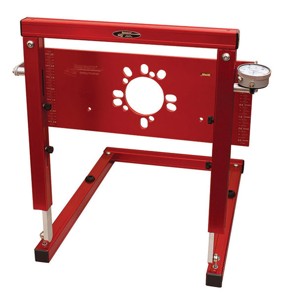
Road racers measure bump-steer with dial indicators although I'm unaware of any standard for what radial distance it is measured at. If you think about it, it's kinda screwy to be measuring an angular occurrence with a linear measurement, but that is the std. By default I suspect most road racers use something like this: https://www.pegasusautoracing.com/productdetails.asp?RecID=880
3178-2015.JPG

Keep in mind that a road racer might have 4" of total wheel travel.

That level of precision isn't really noticeable in the dirt. Maybe on a smooth dirt oval, maybe, but not likely anywhere else.

Ever driven a camber comp'd TTB on the pavement? @lars has driven mine, I'm pretty sure that he's not a fan. They aren't the most precise tracking suspension ever developed. Not by a long shot. Don't even notice this trait going slow or at speed in the dirt.

Find a copy of any of the "Dezert People" movies and look for a head-on or cornering shot of something like a Class 1 car or a Trophy Truck at speed in the rough. Shots from the front make it easy for you to see how much bump-steer they have, and how little it affects the vehicle's trajectory.
 
OP
OP
K

ksagis

Contributor
Aspiring Bronco Guru
Joined
Jun 15, 2020
Messages
818
Loc.
Austin
Road racers measure bump-steer with dial indicators although I'm unaware of any standard for what radial distance it is measured at. If you think about it, it's kinda screwy to be measuring an angular occurrence with a linear measurement, but that is the std. By default I suspect most road racers use something like this: https://www.pegasusautoracing.com/productdetails.asp?RecID=880
3178-2015.JPG

Keep in mind that a road racer might have 4" of total wheel travel.

That level of precision isn't really noticeable in the dirt. Maybe on a smooth dirt oval, maybe, but not likely anywhere else.

Ever driven a camber comp'd TTB on the pavement? @lars has driven mine, I'm pretty sure that he's not a fan. They aren't the most precise tracking suspension ever developed. Not by a long shot. Don't even notice this trait going slow or at speed in the dirt.

Find a copy of any of the "Dezert People" movies and look for a head-on or cornering shot of something like a Class 1 car or a Trophy Truck at speed in the rough. Shots from the front make it easy for you to see how much bump-steer they have, and how little it affects the vehicle's trajectory.
I have seen that in videos! Think you’re spot in that in dirt the effect is greatly diminished.

I’ve love to model a factory, unlifted Bronco if anybody has one we can measure to see what the OEM setup had for bumpsteer
 
Top