JSmall
Bronco Guru
- Joined
- Feb 18, 2004
- Messages
- 3,223
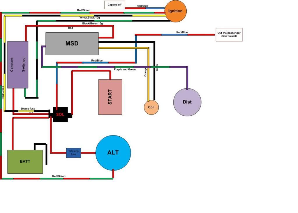
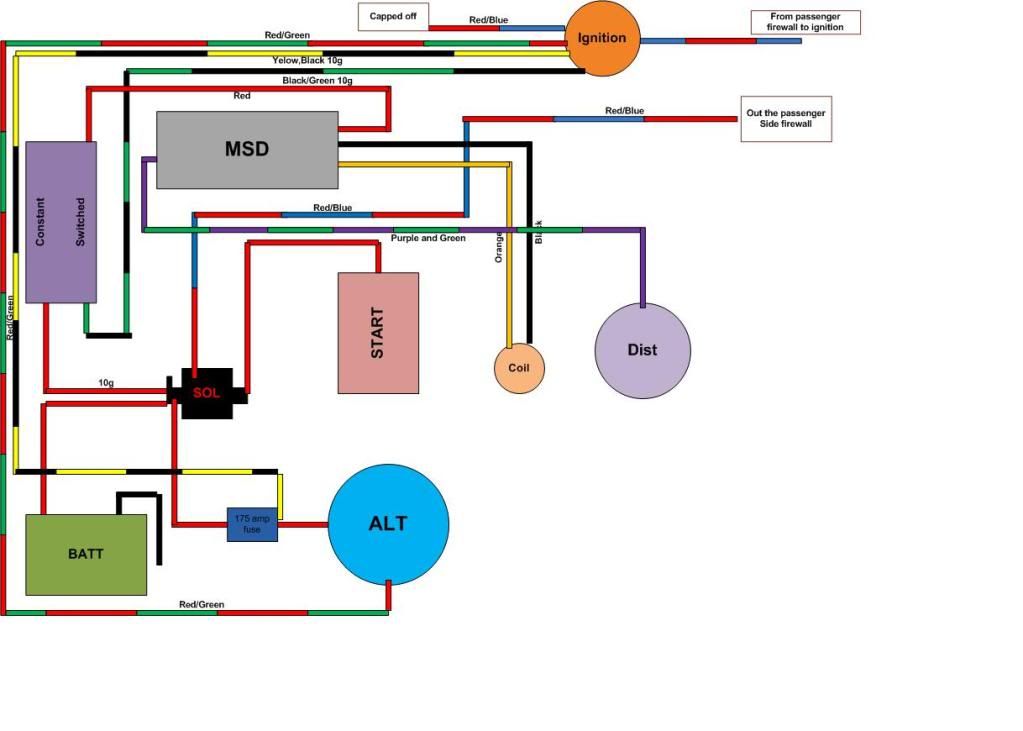
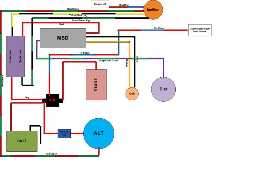
Please excuse my horrible attempt at a wiring diagram. I’ll try to clean it up when I have a good idea of what is going on. My main concern is the wiring from the Fuse box to ignition. Currently I have the Black/yellow wire coming from the B+ side of the solenoid and it runs to the gauge cluster which is capped off because I’ll be running a voltmeter. There is a smaller yellow wire running to the ignition from the Black/yellow wire. If I change it to the setup in the diagram does anybody see any issue that would come up? I know I’ll need to run everything coming off the black/yellow back to the fuse box. I also need to figure out why the red/blue is capped off right out of the ignition.
I have to redo what I’ve already done because my stock fuse block was bad and I didn’t find that out until I was finished. I want to do this one more time and I want it to be perfect. With the Painless fuse box I should have plenty of circuits to do this correctly. Even if it means starting from scratch.
Any help would be greatly appreciated. I will update the drawing with any suggestions and use the final when I’m installing the fuse box this weekend.
Thanks