• Welcome to ClassicBroncos! - You are currently viewing the forums as a GUEST. To take advantage of all the site features, please take a moment to register. It's fast, simple and absolutely free. So please join our community today!
    If you have problems registering or can't log into your account, please contact Admin.

Prop Valve Warning Light Wiring

MIDEVIL214

Jr. Member
Joined
Feb 7, 2005
Messages
166
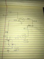
I have an aftermarket CPP brass disk/drum prop valves with a one wire connection. It's been years since I messed with the OEM distribution/h-block wires but I seem to recall a two post connection there. (74 Bronco). I only have one wire down there currently so do I just need to run a splice so I have purple going back to the lamp/bulb and the ignition switch. I'm sure the second half of that wire is still under the dash somewhere.
 

jamesroney

Contributor
Sr. Member
Joined
Sep 11, 2007
Messages
1,736
Loc.
Fremont, CA
The circuit drives me crazy, because I just had to deal with this last weekend. The brake lamp warning circuit is wired backwards to most. Meaning that the bulb filament is powered, but the circuit ins not complete until the other half of the filament is grounded. That ground can either happen at the h-block switch, or it happens on that funny "extra" terminal on the ignition switch. That wire does not get power from the switch. It uses the extra terminal on the switch to connect to GROUND when you put the key in the start position.

For whatever reason, Ford decided to make the splice for that wire in the h-block switch itself. So while there are two terminals...they are actually connected together in the switch. When the switch is "made" then it grounds BOTH terminals. It's clever, but not obvious...so it confuses everyone.

My new prop valve also just has one wire. You just need to splice all 3 together in one junction.

I hope that make sense.
 
OP
OP
MIDEVIL214

MIDEVIL214

Jr. Member
Joined
Feb 7, 2005
Messages
166
So only having one wire down at the prop valve/h block location is correct? The two terminal connection/post was just for the factory distribution block? I swapped the OEM h block for this valve a long time ago but don't remember removing any wires.

I got a new bezel for the warning light so I wanted to test everything after install. With the key in the run position the light would not come on. I had the plunger sensor/switch removed from the CPP prop valve and was manually pushing the pin in/out to simulate the triggering movement. It didn't come on in the compressed or extended position.
 

jamesroney

Contributor
Sr. Member
Joined
Sep 11, 2007
Messages
1,736
Loc.
Fremont, CA
So only having one wire down at the prop valve/h block location is correct? The two terminal connection/post was just for the factory distribution block? I swapped the OEM h block for this valve a long time ago but don't remember removing any wires.

I got a new bezel for the warning light so I wanted to test everything after install. With the key in the run position the light would not come on. I had the plunger sensor/switch removed from the CPP prop valve and was manually pushing the pin in/out to simulate the triggering movement. It didn't come on in the compressed or extended position.
Having one wire at the prop valve is acceptable. The two terminal connection post was just a convenient place to connect the two wires that run down there.

The light will only illuminate when the key is in the "Start" position, or when the plunger is pushed up.

I can draw the schematic of the circuit if it will help you. Let me go find a 1974 wiring diagram to get you the right wires...
 

jamesroney

Contributor
Sr. Member
Joined
Sep 11, 2007
Messages
1,736
Loc.
Fremont, CA
Having one wire at the prop valve is acceptable. The two terminal connection post was just a convenient place to connect the two wires that run down there.

The light will only illuminate when the key is in the "Start" position, or when the plunger is pushed up.

I can draw the schematic of the circuit if it will help you. Let me go find a 1974 wiring diagram to get you the right wires...
Here's a link to a color schematic, and here's a pic. You can see that the two purple/white wires (#977) are connected together inside the switch.

[/URL]
 

Attachments

  • 84CE0169-F562-4A67-8A6D-9619C2B05CE5.jpeg
    84CE0169-F562-4A67-8A6D-9619C2B05CE5.jpeg
    136.7 KB · Views: 11
OP
OP
MIDEVIL214

MIDEVIL214

Jr. Member
Joined
Feb 7, 2005
Messages
166
Thanks for the assistance, just found that schematic myself. Perplexed that the light won’t illuminate when trying to activate the switch plunger manually. It is removed from the valve and that diagram appears to show it ground there. Maybe I just answered my own question.
 

jamesroney

Contributor
Sr. Member
Joined
Sep 11, 2007
Messages
1,736
Loc.
Fremont, CA
Thanks for the assistance, just found that schematic myself. Perplexed that the light won’t illuminate when trying to activate the switch plunger manually. It is removed from the valve and that diagram appears to show it ground there. Maybe I just answered my own question.
Yes. As soon as you remove the switch from the valve...you remove the only source of ground.

If you activate the plunger by pushing it on a grounded conductor...(like the intake manifold) then it will ground the pins...and ground the lamp and light the bulb.
 
Top