


Speedometer Rebuild 101
Tech article by Jeepster and filed under - Dash & Guages, InteriorTech article by Dan Thomas (Jeepster)
For those of you that want to refurbish your Stock Gauge cluster, or want to reset your odometer to reflect a motor rebuild or gauge swap. (Seeing as these Rigs are well over 25 years old, most states usually dont see mileage as an issue on sales and titles…..So when buying an old rig, Let the general condition be your guideline and not what shows on the Odometer. And if you ever sell your vehicle be sure to disclose any modifications you’ve done to the odometer reading.)
-
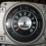
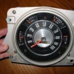
- Stock cluster out of a 74 showing 75152 mi.
-
- Now odometer can be removed.
-

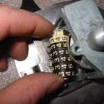
- I found this to be the best way to hold the numbers.
-
- Metal tabs lined up. Another view.
-
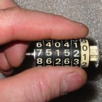
- If you want to change the odometer (replacing to match old, or reset) Hold the metal tabs in your left hand…
-
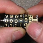
- …while rotating the remainding tabs with the other hand…
-

- …working left to right till you are where you want to be.
-

- Check the plastic gears for good condition.
-

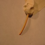
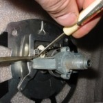
- Insert a small screwdriver in the cable slot and turn to check for smooth operation. Needle should move freely and return to zero.
-

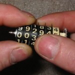
- Insert numbers back into unit.
-
- Be careful to keep tabs lined up. The tab notches must engage the metal edge (check all of them).
-
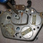
- Remove 4 phillips screws.
-
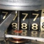
- Notches along “8’s”.
-
- Reinstall clip.
-

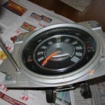
- Check to see that you got it right.
-
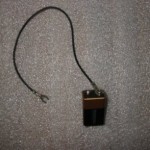
- If your dealing with a used replacement cluster now is a good time to check the other gauges. This is my gauge checking tool. 9v battery,some wire.
-
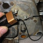
- This setup will work on Fuel,oil,and temp. (The amp gauge will have to have a wire with current inserted into its loop) Place wire on 1 post of gauge while touching the other post of battery to the remaining post of the gauge.
-

- You should see movement.
-
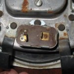
- This is the Constant Voltage Unit It supplys power to the gauges. The right terminal is marked “IGN”
-
- This is how I tested the unit (note: I’m not an electrical engineer so my observations or method are not necessarily science) 12V battery “pos +” to “IGN” terminal on C/V unit 12V test light to C/V unit case or ground. other end of test light to battery “Neg -” Opon completing the circuit the test light will light steady for a few seconds then flicker or blink as the C/V unit regulates the power. indicating a good unit.
-

- The needles on the gauges were faded…
-
- so I removed them to freshen up.
-

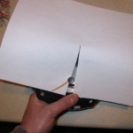
- Seperate front cover with glass.
-
- They are held in place with (2) 1/4″ screws each. Mask. (careful needles are fragile)
-
- My spray booth.
-
- I used florescent orange. Spray lightly. Dont use too much paint.(it might throw off readings)
-
- Now is also a good time to freshen up the face plate. I believe Argent paint would be the color you would want to match. This one was good so I will use it as is. Ready for reassembly.
-
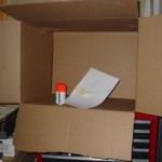
- (dont forget the carboard tubes for the lights) Ready to put back in dash.
-

- You will also have a intermediate cover.
-
- On the back remove the 2 slotted screws.
-

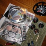
- 4 main pieces.
-

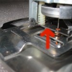
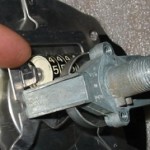
- To remove odometer numbers this clip must be removed. Take a screwdriver…
-
- …and push the legs of the back of the clip off of the metal while with a second small screwdriver bending the front of the clip off of the odometer shaft.
-

- Clip.
May 28th, 2009 at 11:05 pm
Dan: Very good tech tips on the Bronco speedometer. However when I took mine apart I had a half moon insert between the glass panel and the shiney panel that you show in your break down. This half moon insert was not mentioned in your article? Also you didn’t mention the turn signal small greem plastic covers. Are these available anywhere?
Thanks
RVH
May 29th, 2009 at 3:53 am
Thank you for the compliment. I’m assuming the “1/2 moon insert” is the piece that is between the glass and the speedometer face. From reviewing the photos as I see it, This ring’s purpose is to mask the gages for a finished look. It also holds the two green and 1 red filter. (turn signal and high beam indicator lights) I’m sorry this piece was not mentioned as it was in good shape and didn’t need attention. Other that maybe having to repaint the ring to freshen it up some,which it didn’t need, there was little to do with it.
Addressing the green filters for the turn signals. From memory I believe they were just a plastic like tape applied over the holes. Not available, I assume, from Ford and I haven’t seen any offered from venders. Not to say that something isn’t out there. Perhaps I would look at any colored cellophane clear tapeof the right color or maybe stage lighting gel filters that one could cut a small piece to affix over the holes.
Dan
June 7th, 2009 at 11:42 am
Great article. The only thing I would add is that before reassembly, apply two or three drops of three-in-one oil to the speedodometer needle shaft. This will prevent needle bounce as the needle sweeps up.
August 30th, 2009 at 3:32 am
I replaced the little red & green lenses with the colored translucent plastic from the caps to cinnamon & spearmint mint gum/mint containers… check the grocery store.
Just trim out a piece and then use hot glue around the edges to cover the hole where it goes. I changed the red high beam to blue (to match my truck)… but i did find the red plastic as well.
Hope this helps
December 31st, 2009 at 3:22 pm
Thanks for the write up. I followed it step by step and the speedo looks brand-new.
August 24th, 2010 at 10:02 am
Anyone know where I can get a piece of glass for mine? When I got my 71 the glass was broken.
Thanks,
February 21st, 2012 at 7:06 pm
Young Army Vet..LMC now carries glass.
Also, when handling the inner metal face plate make (the one with numbers printed on) DO NOT push down so as to interfere with speedo needle rotation. This will cause the very small watch spring (speedo needle return spring) to bind and it will twist in very short order. The speedo “calculates” actual speed via the spring and a counter rotation on the drum at the rear of the unit. These two forces are calibrated and any change in that springs tension will throw off the readings big time!. My speedo had to be sent out to a specialty shop to replace the spring..still waiting to hear how much it’s going to cost for my little mistake.
November 16th, 2013 at 11:33 pm
[…] then a part. Some people reset the odometer after a major rebuild/restore. Check out this link. Speedometer Rebuild 101 | ClassicBroncos.com Tech Articles I would like to restore an '72 or earlier VW Bus. But they are crazy expensive. '64 is my birth […]
December 26th, 2013 at 8:32 pm
For rebuild parts go here…..
http://www.classychassisrestoration.com/products/